Optical fiber digital transmission method applied on straight-forward station

A transmission method and repeater technology, applied in transmission systems, radio transmission systems, electrical components, etc., can solve problems such as inability to digital peak clipping, digital predistortion, inflexibility, and reduced signal-to-noise ratio.

Active Publication Date: 2009-07-22
CHINA YOUKE COMM TECH
View PDF0 Cites 11 Cited by
  • Summary
  • Abstract
  • Description
  • Claims
  • Application Information

AI Technical Summary

Problems solved by technology

The disadvantages of this are: ①The attenuation of the optical signal is relatively large, ②The signal-to-noise ratio of the radio frequency signal carried by the optical signal decreases during the attenuation of the optical signal, ③The network allocation of frequency selection and frequency points can only be realized in analog devices, There is no flexibility, ④ there is no digitalization of the signal, and there is no way to use advanced technologies such as digital peak clipping and digital pre-distortion commonly used in the CDMA system

Method used


Image

  • Optical fiber digital transmission method applied on straight-forward station
  • Optical fiber digital transmission method applied on straight-forward station
  • Optical fiber digital transmission method applied on straight-forward station

Examples


Embodiment Construction

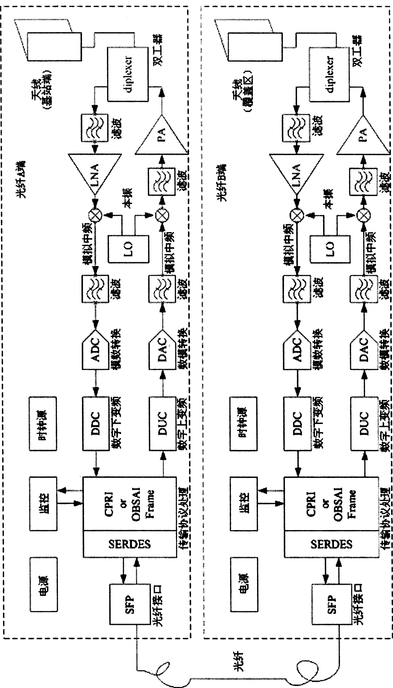
[0014] Taking CDMA2000 Repeater 3 carriers as an example, the implementation of the system is as follows.

[0015] In the downlink, the fiber A end receives the radio frequency signal from the antenna facing the base station or the coupler attached to the antenna, and outputs an analog intermediate frequency of 70-140MHz after filtering, low-noise amplification, and analog mixing. Such as figure 1 shown.

[0016] The analog intermediate frequency signal is sampled by a high-speed ADC (generally using under-sampling), converted into a digital signal, and enters the digital signal processing stage.

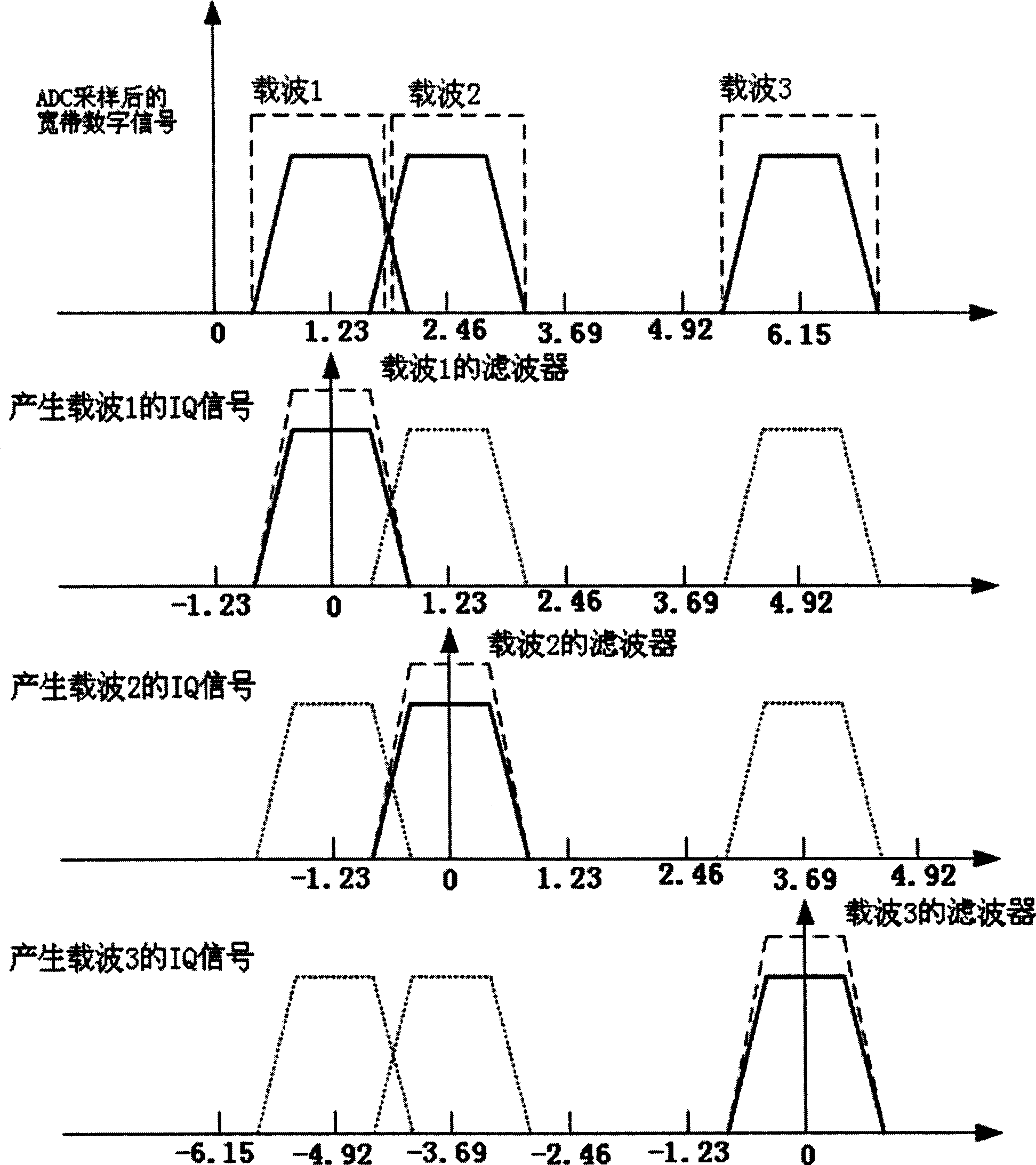
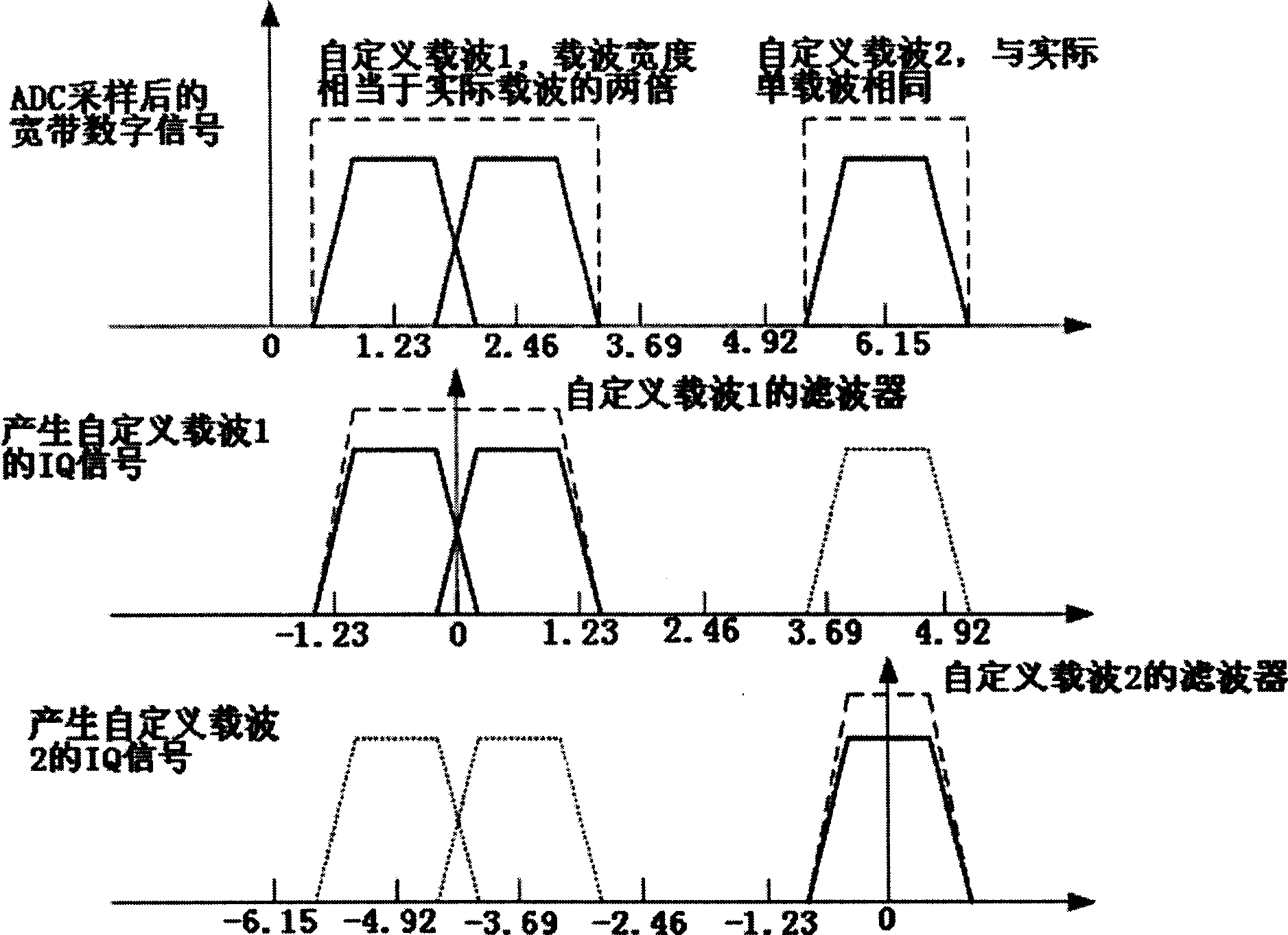
[0017] During digital down-conversion, sampling-flexible digital mixers and digital filters move the carrier to baseband. Such as Figure 2a As shown, the three carrier centers are located at 1.23MHz, 2.46MHz and 6.15MHz respectively. According to the usual processing method, three channels can be used to process three carriers respectively, each channel contains an independent ...


PUM


Abstract

The invention relates to an optical fiber digitalization transmission method applied to straight amplification station, the method comprises: converting a radio frequency signal of a signal source into an IF signal and a broad band digital signal; separating and moving the known carrier wave in the broad band digital signal into the baseband by digital down-conversion; packing the baseband signal and the monitoring signal into CPRI or other standard high speed serial protocol data and transmitting into the other compatible apparatus by optical fiber; de-packing the CPRI or other standard high speed serial protocol data by the compatible apparatus to separate the baseband signal and the monitoring signal; moving each baseband signal into IF, then adding to form a broad band digital intermediate frequency; converting the digital IF signal into a simulation IF signal by a high speed DAC; converting the simulation intermediate frequency into the radio frequency signal, transmitting by the aerial through being amplified by a power amplifier. The apparatus designed by the invention can enable the networking of the optical fiber straight amplifying station to be flexible, thereby greatly improving the engineering debugging simplicity.

Description

technical field [0001] The invention relates to an optical fiber digital transmission method applied to repeaters. Background technique [0002] The repeater (repeater) belongs to the same-frequency amplification device, which refers to a radio transmission relay device that enhances the signal during the wireless communication transmission process. The basic function of the repeater is a radio frequency signal power booster. In the downlink of the repeater, the signal is picked up from the existing coverage area of ​​the donor antenna, and the signal outside the band pass is excellently isolated through the band pass filter, and the filtered signal is amplified by the power amplifier and then transmitted to the standby coverage area. In the uplink path, the signal of the mobile phone in the coverage area is processed by the uplink amplification link in the same way and then transmitted to the corresponding base station, so as to achieve the signal transmission between the...

Claims


Application Information

Patent Timeline
Patent Type & Authority Applications(China)
IPC IPC(8): H04B7/155
Inventor 赖克中张健荣余俊翟红光王瑶宝
Owner CHINA YOUKE COMM TECH
Why Eureka
Try Eureka