Mounting method using thermocompression head

A technology of hot-pressed joint and installation method, which is applied in the direction of assembling printed circuits, presses, and printed circuits with electrical components, can solve the problems of reduced connection reliability, insufficient heating, and installation takes a long time, and achieves high reliability. Sexual connection, the effect of preventing the generation of voids

Inactive Publication Date: 2009-07-22
DEXERIALS CORP
View PDF1 Cites 10 Cited by
  • Summary
  • Abstract
  • Description
  • Claims
  • Application Information

AI Technical Summary

Problems solved by technology

[0007] [0005] However, when using a crimping head formed of metal, ceramics, etc., voids may be generated due to insufficient heating of the fillet portion of the adhesive around the electrical component during thermocompression bonding, which may cause reliable connection. problem of reduced sex
[0008] On the other hand, when the crimping head formed of the above-mentioned elastic body is used, since the heating of the crimping head side is not sufficient during thermocompression bonding, there will be a problem that it takes a long time for installation.

Method used


Image

  • Mounting method using thermocompression head
  • Mounting method using thermocompression head
  • Mounting method using thermocompression head

Examples


Embodiment Construction

[0037] [0013] Hereinafter, an embodiment of the installation method of the thermocompression joint according to the present invention will be described in detail with reference to the accompanying drawings.

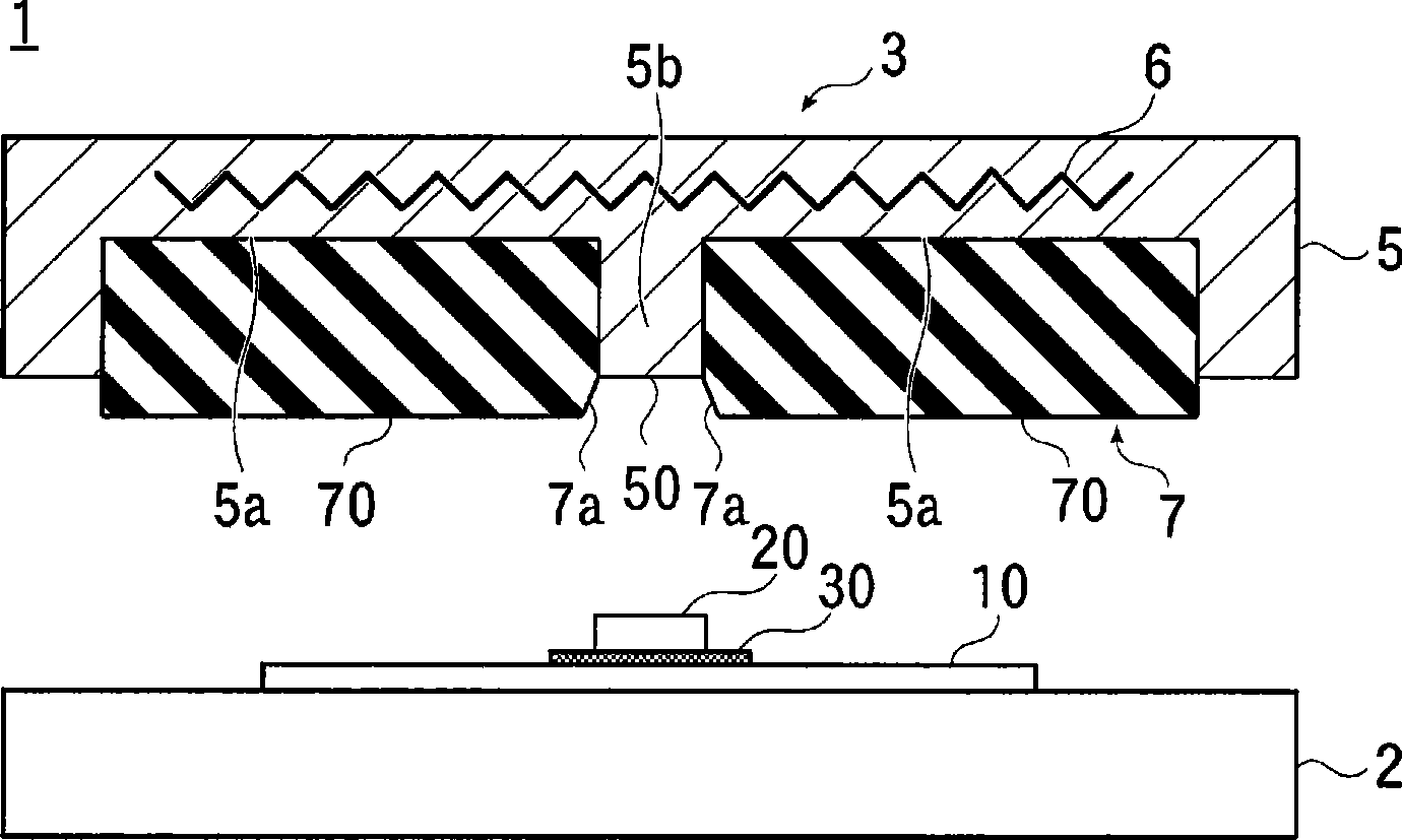
[0038] [0014] FIG. 1(a) is a schematic partial sectional view showing a mounting device according to the present invention, and FIG. 1(b) is a view showing a pressing side portion of a thermocompression joint in the mounting device.

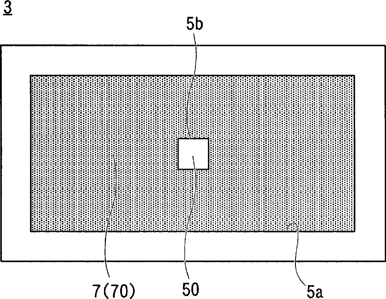
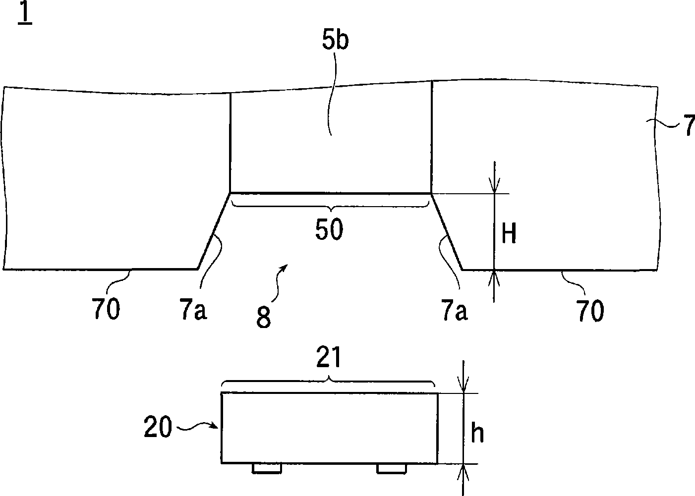
[0039] also, Figure 2(a) , 2(b) It is an explanatory diagram showing the dimensional relationship between the pressing surface of the thermocompression joint and the top area of ​​the electrical component.

[0040] 【0015】if Figure 1(a) , 1(b) As shown, the mounting device 1 of the present embodiment has: a base 2 on which a wiring substrate 10 is mounted and a wiring pattern (not shown) is formed on the wiring substrate 10; Electric components 20 such as IC chips are pressurized and heated.

[0041] [0016] Here, the base 2 is formed of...


PUM


Abstract

Provided is a mounting method using a thermocompression head which can mount an electric component in a short time with high connection reliability. The method is provided for mounting an electronic component (20) on a wiring board (10) by using a thermocompression head (3) having an elastic pressure bonding member (7) composed of an elastomer on a heatable metal head main body (5). In the method, after arranging an adhesive on a mounting region on the wiring board (10), an electric component (20) is arranged on a mounting region, and the electric component (20) is bonded on the wiring board (10) by thermocompression by using the thermocompression head (3). At the time of performing thermocompression bonding, while pressing a top region (21) of the electric component (20) by a metal portion of the head main body (5), an adhesive (30) in the vicinity of a side portion region (22) of the electric component (20) is pressed by a taper section (7a) of the elastic adhesive member (7).

Description

technical field [0001] [0001] The present invention relates to a technique for installing various electrical components on a wiring substrate, and in particular to a method for installing a thermocompression joint using an adhesive to install electrical components. Background technique [0002] [0002] Generally, when mounting driven elements such as resistors and capacitors on a wiring board, the mounting is carried out by melting solder as a connection material in a reflow furnace. [0003] [0003] On the one hand, when electrical components such as IC chips are mounted on a wiring board, they are packaged and mounted by soldering, and the IC chips are directly mounted on the wiring board, and can be mounted by wire bonding or flip-chip. [0004] When these electrical components are flip-chip mounted using conductive adhesives, hard crimping joints such as metal and ceramics are usually used for thermocompression bonding. [0005] [0004] On the other hand, in recent years, ...

Claims


Application Information

Patent Timeline
Patent Type & Authority Applications(China)
IPC IPC(8): H01L21/60H01L21/603H05K3/32
CPCH01L2224/75252H05K2203/1189H01L24/83H01L2924/0781B30B5/02H05K3/305H05K3/328H01L2224/83101H01L2924/01004H01L2224/75304H01L2924/01006H05K2201/10977H01L2924/19041H01L2924/14H01L2224/16H01L2224/83192H01L2924/01005H01L2224/73204H01L2224/75303H01L2224/75H05K2201/10674H01L2924/014H01L2924/07811H01L24/90H01L2224/838H01L2924/19043B30B15/065H01L2924/01033H01L2224/75315H01L24/75H01L2924/01075H01L2224/75316H01L2924/07802H01L2924/00H05K3/32
Inventor 古田和隆谷口雅树
Owner DEXERIALS CORP
Why Eureka
Try Eureka