Connector for connecting electronic component

A technology for electronic components and connectors, applied in the direction of two-component connection devices, connections, electrical components, etc., can solve problems such as radiation noise, and achieve the effect of reducing noise radiation

Inactive Publication Date: 2009-07-22
MITSUMI ELECTRIC CO LTD
View PDF3 Cites 8 Cited by
  • Summary
  • Abstract
  • Description
  • Claims
  • Application Information

AI Technical Summary

Problems solved by technology

[0006] In this case, as for the connector, since the lead part connected to the contact terminal of the substrate flows through the high-speed signal, in the structure where the lead part is arranged on the contact terminal of the substrate for bonding, since the lead part is exposed to the outside, there is a Potential issue with radiated noise

Method used


Image

  • Connector for connecting electronic component
  • Connector for connecting electronic component
  • Connector for connecting electronic component

Examples


Embodiment approach 1

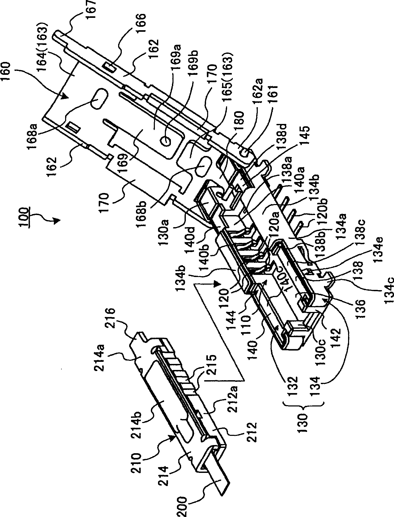
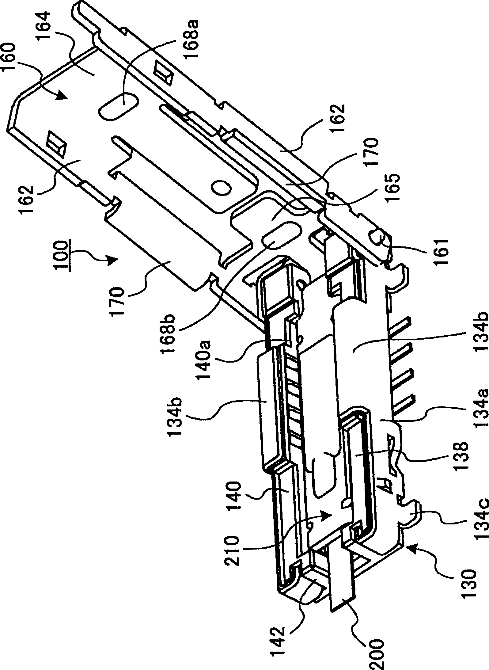
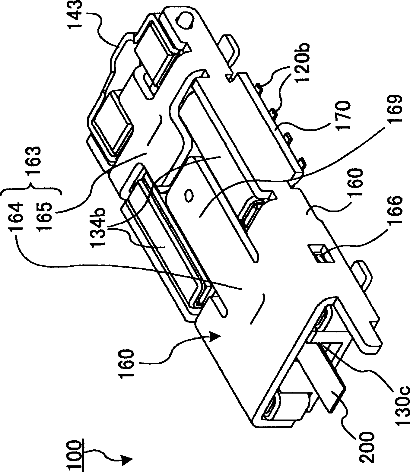
[0026] figure 1 It is a configuration diagram showing the electronic component connection connector 100 according to Embodiment 1 of the present invention. Here, a module on which an optical waveguide is mounted will be used as an electronic component connected to the electronic component connector 100 . Furthermore, in this embodiment, the surface on which the electronic component connection connector 100 is mounted on the substrate is defined as the bottom surface, and the direction in which the optical waveguide 200 is mounted on the module (electronic component) 210 is defined as the front end direction. In addition, the electronic component is not limited to a module with an optical waveguide, and may be a module including an electric wire, a cable, a flexible cable, or an optical fiber.

[0027] figure 1 In the illustrated connector 100 for connecting electronic components, an optical waveguide 200 that guides an optical signal is joined, and a module 210 that receives...

Embodiment approach 2

[0149] Figure 8 It is a configuration diagram showing a connector for connecting an electronic component according to Embodiment 2 of the present invention, Figure 9 It is a diagram showing that the connector for connecting electronic components is inserted, Figure 10 It is a diagram showing the electronic component connection connector in the state where the module is connected and the cover is closed.

[0150] The connector 300 for connecting electronic components according to the second embodiment is similar to the connector 100 for connecting electronic components according to the first embodiment. In this case, the module 210 on which the optical waveguide 200 is mounted is detachably connected and housed in the connector. inside the opening 310 of the main body 330 (refer to Figure 9 ).

[0151] The electronic component connector 300 is shielded from external electric and magnetic fields by covering the module 210 housed in the opening 310 with a cover member (cov...

Embodiment approach 3

[0229] Figure 11 It is a configuration diagram showing a connector for connecting an electronic component and an electronic component accommodated in the connector according to Embodiment 3 of the present invention, Figure 12 is viewed from behind Figure 11 The perspective view of the connector for connecting electronic components and the electronic components shown.

[0230] The connector 400 for connecting an electronic component according to Embodiment 3 differs from the connector 300 for connecting an electronic component having the same basic structure as the connector 100 for connecting an electronic component in that the receptacle contact portion (contact Terminals) are increased in number and have positioning protrusions 460 (462, 464, 466), and other structures are the same. Therefore, different constituent elements will be described below, and constituent elements that are the same as those in the electronic component connector 300 will be assigned the same nam...


PUM


Abstract

Provided is a connector for connecting an electronic component, which reduces noise radiation when the electronic component is connected to a substrate through the connector and driven. In a connector (100), a connector main body (130) stores a module (210) inside an opening section (110), and the connector main body is mounted on the substrate by being electrically connected to the stored module (210). The connector main body (130) is provided with a contact lead section (120b) which is lead out to the side of the connector main body (130) to be bonded to a conductor on the substrate. A cover member (160) which opens and closes by turning with a shaft section (161) at the center is pivotally supported on the connector main body (130), and the opening section (110) is covered with the cover member (160) from above. The cover member (160) is provided with a conductive skirt section (170) for covering the contact lead section (120b) from above in a closed state.

Description

technical field [0001] The present invention relates to a connector for connecting an electronic component to an electronic component such as a module in which an optical waveguide or the like is coupled to a signal transmission component. Background technique [0002] Conventionally, when an electronic component is detachably mounted on a substrate for maintenance or the like, a method of providing it on the substrate via a connector is known. [0003] At this time, the connector is generally detachably electrically connected to the electronic component, and the lead part extending from the lower part in the horizontal direction is arranged on the contact terminal on the substrate for bonding, thereby performing substrate mounting (for example, refer to Patent Document 1-Japanese Japanese Patent Laid-Open No. 2005-56626). [0004] However, along with the miniaturization of electronic devices such as mobile phones, the miniaturization of electronic components mounted on the...

Claims


Application Information

Patent Timeline
Patent Type & Authority Applications(China)
IPC IPC(8): H01R33/74H01R13/648H01L23/32
CPCH01R12/716H01R23/701H01R12/7011G02B6/4201H01R23/6873G02B6/4284H01R13/658
Inventor 西尾敦浅野信一石川贵启中根健智
Owner MITSUMI ELECTRIC CO LTD
Why Eureka
Try Eureka