
High frequency circuit module

a high-frequency circuit and module technology, applied in the direction of high-frequency circuit adaptation, printed circuit non-printed electric components association, semiconductor/solid-state device details, etc., can solve the problems of noise or leakage signal generation, conventional technology is not capable of properly meeting the latest demands for smaller and more highly integrated mobile phones, etc., to reduce power loss and noise radiation, increase density, and prevent noise

Active Publication Date: 2014-05-15
TAIYO YUDEN KK
View PDF5 Cites 7 Cited by
  • Summary
  • Abstract
  • Description
  • Claims
  • Application Information

AI Technical Summary

Benefits of technology

The present invention provides a structure for reducing the length of the signal wire that connects a duplexer to a power amplifier IC, which helps to minimize power loss and noise. The transmission signal from the power amplifier IC passes through the duplexer without being amplified, so it has a small impact on the duplexer and other circuits. The ground electrode on the circuit substrate is connected to a heat dissipation electrode of the power amplifier IC through a via conductor, which improves heat dissipation efficiency. This structure allows for miniaturization, increased density, and reduced power loss and noise in the reception circuit of the high frequency IC.

Problems solved by technology

However, conventional technology is not capable of properly meeting latest demands for smaller and more highly integrated mobile phones.
Thus, noise or a leakage signal generated by the power amplifier IC is likely to enter into a receiving circuit of the high frequency IC.

Method used


Image

  • High frequency circuit module
  • High frequency circuit module
  • High frequency circuit module

Examples


embodiment 1

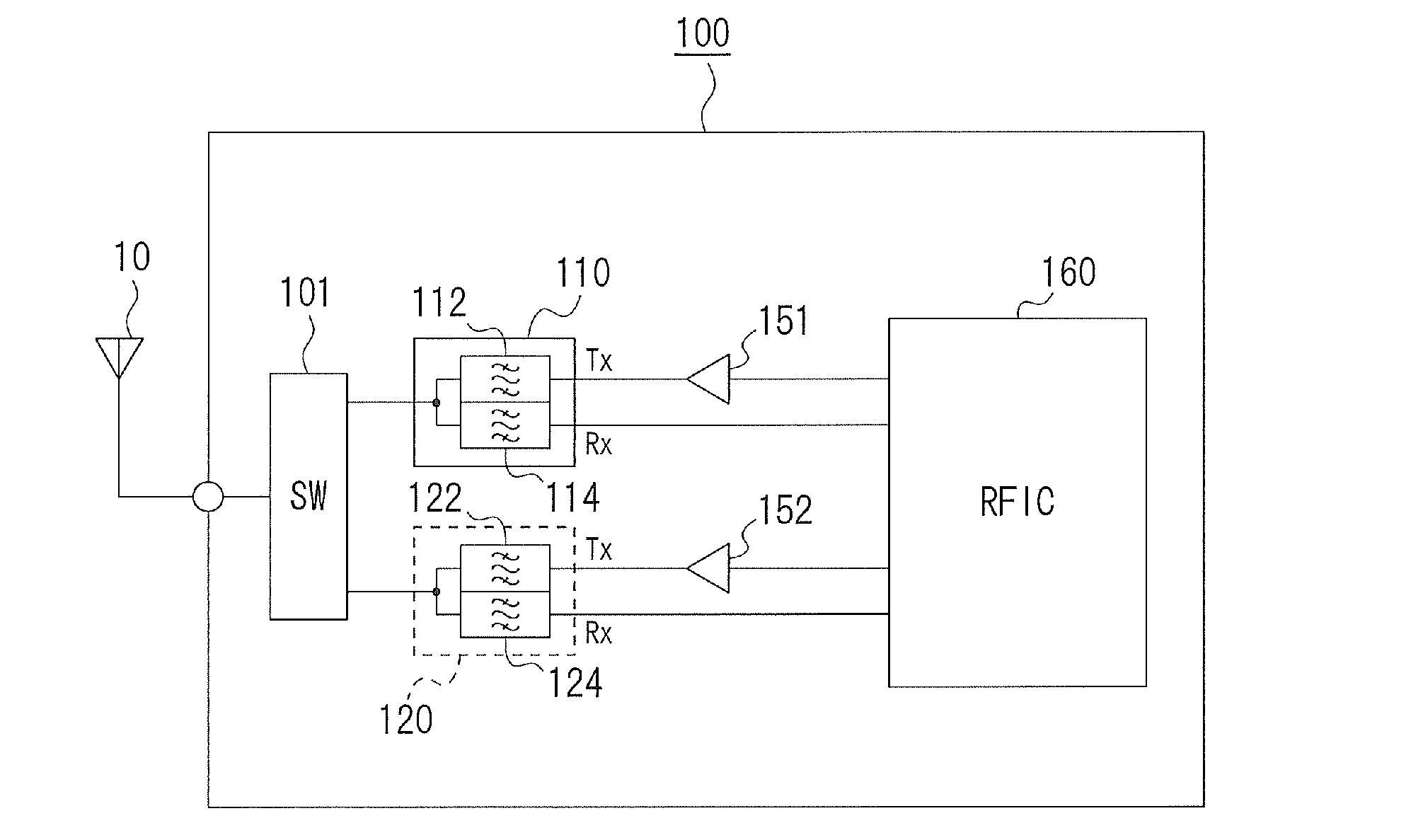
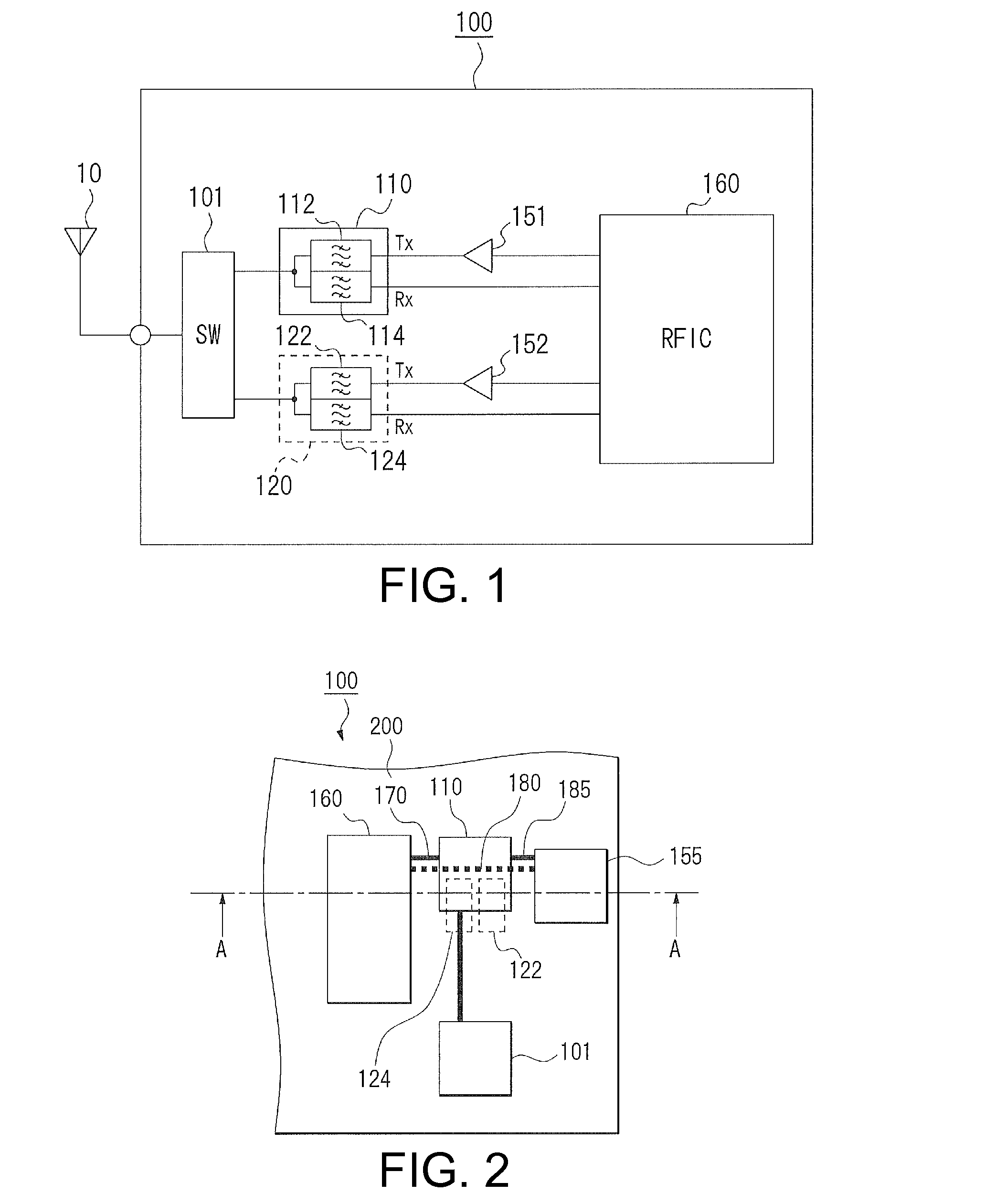
[0029]A high frequency circuit module according to Embodiment 1 of the present invention will now be described with reference to accompanying drawings. FIG. 1 is a circuit diagram schematically illustrating a high frequency circuit module. The description of Embodiment 1 will be focused on the main constitution of the present invention for simplification.

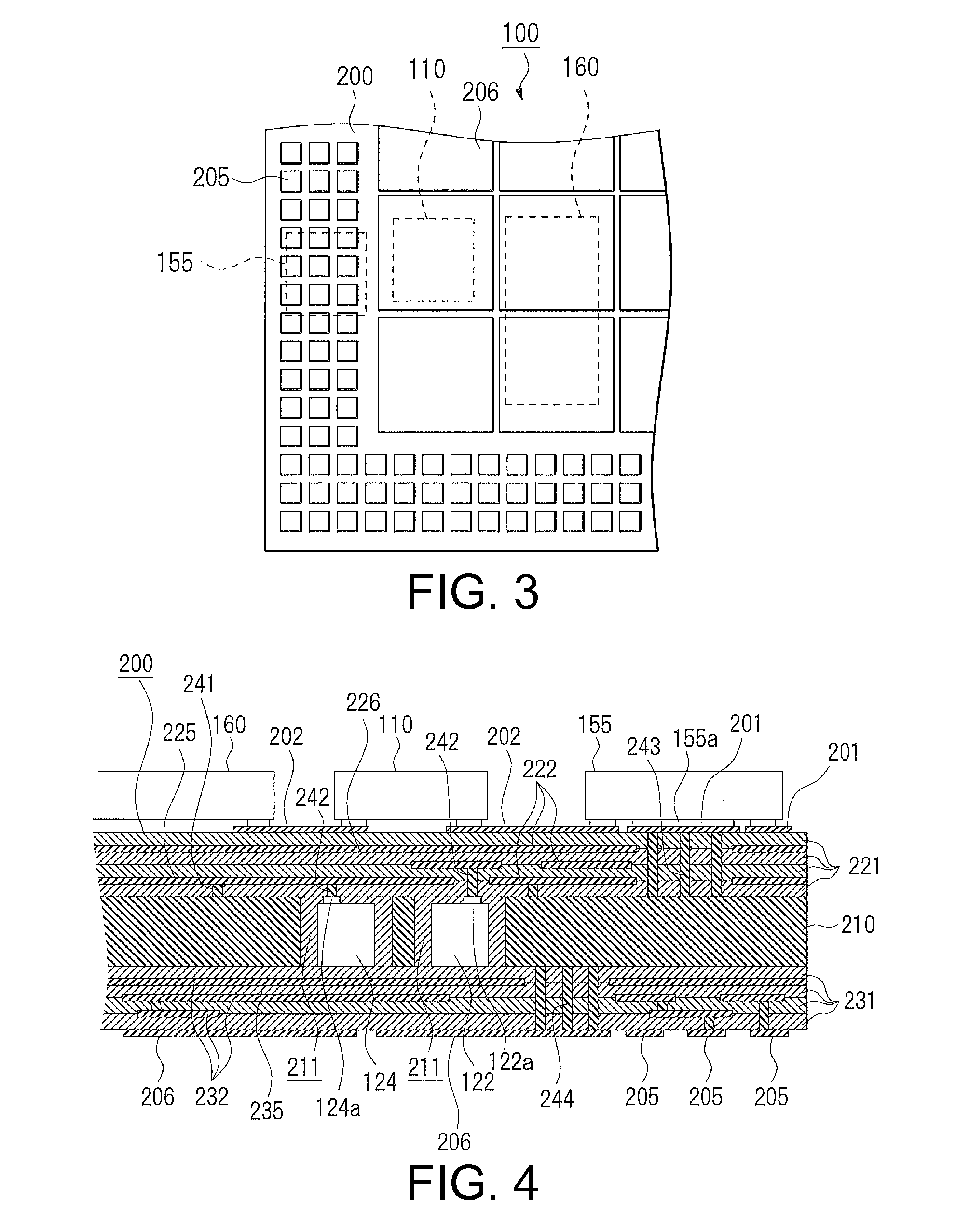
[0030]A high frequency circuit module 100 according to Embodiment 1 is preferably used in mobile phones employing two frequency bands. As shown in FIG. 1, the high frequency circuit module 100 includes a high frequency switch 101, a first duplexer 110, a second duplexer 120, high frequency transmission power amplifiers 151 and 152 for transmission, and a radio-frequency integrated circuit (RFIC) 160. Although the high frequency circuit module 100 includes a matching circuit, a band pass filter for a transmission signal, and the like for each of frequency bands when implemented as an actual circuit, they are omitted in the present em...

embodiment 2

[0042]A high frequency circuit module according to Embodiment 2 of the present invention will now be described with reference to the accompanying drawings. The high frequency circuit module according to Embodiment 2 differs from the high frequency circuit module according to Embodiment 1 in the installation structures of the RFIC and the power amplifier IC. Other aspects such as the schematic circuit diagram of the high frequency circuit module, for example, are similar to that of Embodiment 1, and thus, mainly the difference between the embodiments will be described here.

[0043]The structure of a high frequency circuit module 300 according to Embodiment 2 will now be described with reference to FIGS. 6 to 8. FIG. 6 is a top view of the high frequency circuit module 300. FIG. 7 is a bottom view of the high frequency circuit module 300. FIG. 8 is a cross-sectional view along the line A-A of FIG. 6.

[0044]As shown in FIG. 6, in the high frequency circuit module 300 includes a high frequ...


PUM


Abstract

The high frequency circuit module includes an RFIC configured to transmit and receive a high frequency signal, a power amplifier IC configured to amplify a transmission signal outputted from the RFIC, and a duplexers configured to separate the transmission signal outputted from the power amplifier IC and inputted to an antenna and a reception signal from the antenna and inputted to the RFIC from each other, in which at least one of the RFIC and power amplifier IC is embedded in the circuit substrate, and the duplexers are disposed between the RFIC and the power amplifier IC.

Description

[0001]This application claims the benefit of Japanese Application No. 2012-249160, filed in Japan on Nov. 13, 2012, which is hereby incorporated by reference in its entirety.BACKGROUND OF THE INVENTION[0002]1. Field of the Invention[0003]The present invention relates to a high frequency circuit module in which a high frequency integrated circuit (IC), a power amplifier IC, and a duplexer are mounted on a circuit substrate, and more particularly, to an arrangement of components of a high frequency circuit module.[0004]2. Description of Related Art[0005]Recently, multi-functional mobile phones having a small size, so-called smart phones, are being developed. In such mobile phones, a high frequency circuit module with a circuit substrate having thereon various components for transmitting and receiving a high frequency signal is mounted on a mother board (for example, see Patent Document 1). In a high frequency circuit module disclosed in Patent Document 1, a high frequency integrated c...

Claims


Application Information

Patent Timeline
Patent Type & Authority Applications(United States)
IPC IPC(8): H03H9/70
CPCH04B1/44H04L5/14H01L23/3677H01L2224/16227H01L2924/0002H01L2924/15192H01L2924/15313H01L2924/3511H03H9/0566H04B1/58H05K1/0206H05K1/0243H05K1/185H05K3/4608H04B1/38H05K1/18H01L23/3735H03H1/0007H03H7/463H03H9/08H03H11/344H03H11/348H03H2001/0085H05K1/0207H05K1/0216H05K1/0237H01L2924/00
Inventor NAKAMURA, HIROSHIIGARASHI, TOMOHIRO
Owner TAIYO YUDEN KK
Learn More