Shell main body for muffler

a muffler and shell technology, applied in the direction of liquid fuel engines, machines/engines, rotary piston liquid engines, etc., to achieve the effects of reducing noise radiation, preventing shell deformation, and increasing stiffness

Inactive Publication Date: 2005-11-17
CALSONIC KANSEI CORP
View PDF12 Cites 5 Cited by
  • Summary
  • Abstract
  • Description
  • Claims
  • Application Information

AI Technical Summary

Benefits of technology

[0010] In the above-described shell main bodies of the present invention, the beads are provided in one of the shells to continuously extend in the circumferential direction along the small arc portions of the cylindrical cross section, thereby allowing the upper and lower gaps between the inner shell and the outer shell in the respective large arc portions of the shell main body to communicate with each other through the passages formed by the beads. Further, the communicating path through which the gap between the inner shell and the outer shell communicates with the outside of the outer shell is provided on the upper surface side of the shell main body. This structure allows vapor generated between the inner shell and the outer shell in the lower large arc portion to easily flow into the gap in the upper large arc portion through the passages and to be thereafter discharged out of the shell main body from the communicating path.
[0011] Therefore, in a cylindrical shell main body constituting a muffler main body to be formed by two layers of an inner shell and an outer shell and having a cylindrical shape with a cross section that is not a perfect circle but is defined by alternated small arc portions and large arc portions, similarly to an oval, a racing track, or the like, the above-constructed shell bodies can provide an effect of preventing the deformation of the shell ascribable to vaporization of water entering between the inner shell and the outer shell. Further, the shell with the beads can have increased stiffness, so that noise radiation can be reduced.
[0012] Preferably, the communicating path is formed by a gap that is formed between the inner shell and the outer shell and in places excluding welded portions of the inner shell and the outer shell. Therefore, the communicating path can be formed easily and at a low price, because it removes a special processing, such as a drilling process.
[0013] Preferably, the radially projecting beads are formed in plurality along each of the small arc portions, and being arranged in an axial direction of the shell main body at intervals. Therefore, the beads can prevent deformation along the axial direction of the shell main body due to increase of its axial-directional stiffness.

Problems solved by technology

It is undesirable to provide a lower side of the outer shell 103 with a communicating path connecting the lower gap and the outside of the outer shell 103, because a splash and / or mud is allowed to enter the lower gap through the communicating path and rust the muffler main body.

Method used


Image

  • Shell main body for muffler
  • Shell main body for muffler
  • Shell main body for muffler

Examples


first embodiment

[0023] First, a shell main body for a muffler of a first embodiment will be described with reference to the accompanying drawings of FIGS. 1 to 3.

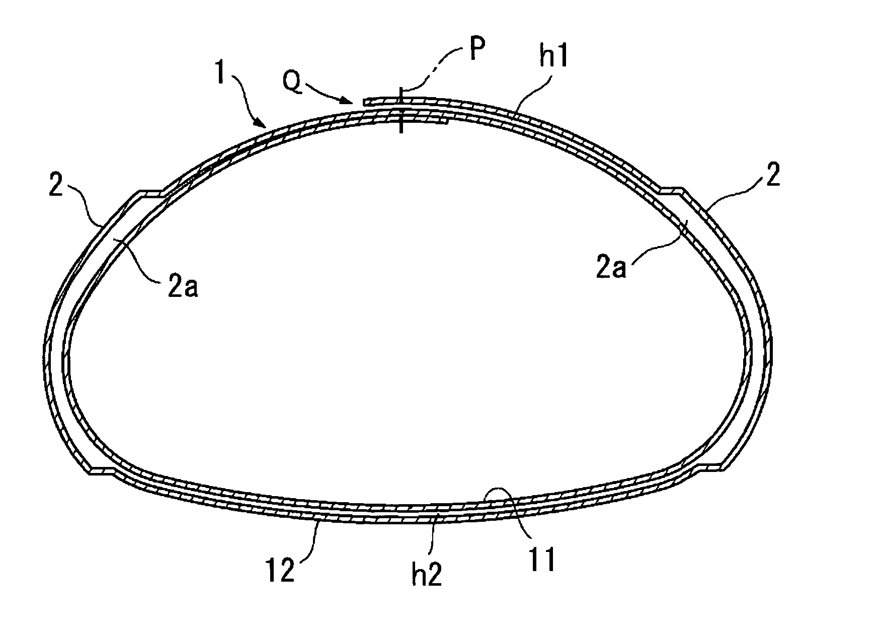
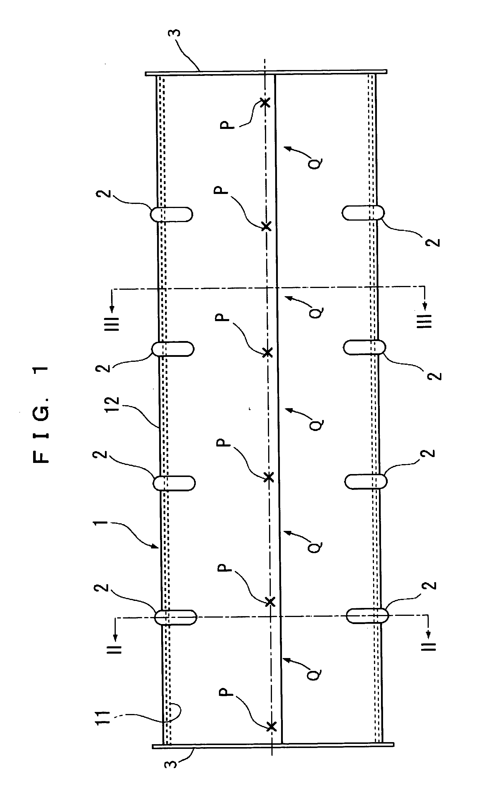
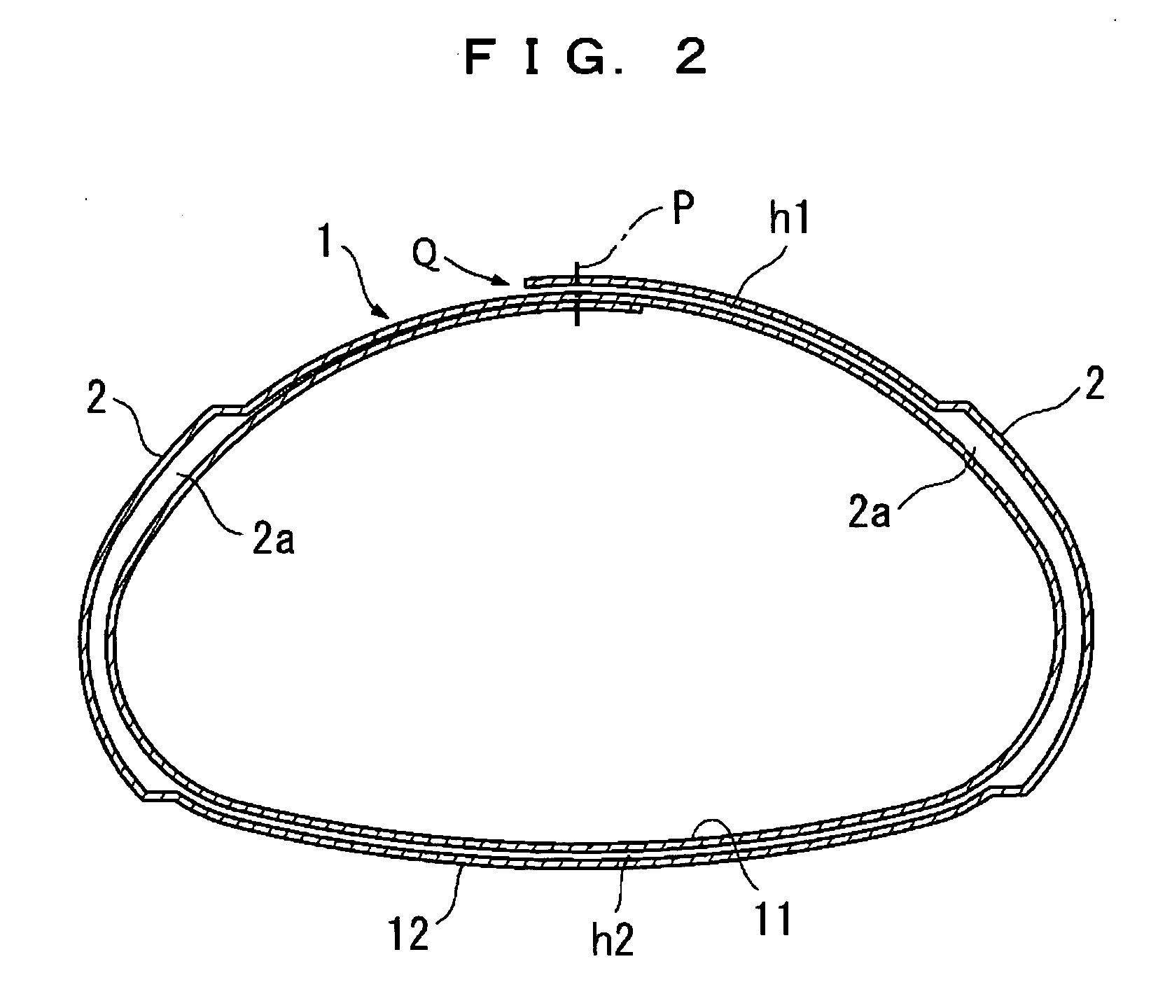
[0024]FIG. 1 is a plane view showing the shell main body of the first embodiment, FIG. 2 is a cross-sectional view showing the shell main body taken along the II-II line in FIG. 2, and FIG. 3 is a cross-sectional view showing the shell main body taken along the III-III line in FIG. 1.

[0025] The shell main body 1 of the first embodiment is used for a muffler main body of an exhaust system mounted on a motor vehicle. The muffler main body is connected at its both ends with not-shown exhaust pipes. The shell main body 1 is made of a double-rolled flat plate, with a joint portion thereof being spot-welded in portions P, and formed of two layers of an inner shell 11 and an outer shell 12 so that it has a laterally long, flattish cylindrical shape with a cross section substantially in a laterally long, rounded triangle shape.

[0026] As describe...

second embodiment

[0036] Next, a shell main body for a muffler of a second embodiment according to the present invention will be described with reference to the accompanying drawings of FIGS. 1 to 6. In describing the second embodiment, similar reference characters and numbers refer to similar elements in all figures of the drawings, and their descriptions are omitted for eliminating duplication.

[0037]FIG. 4 is a partially sectioned plane view showing a shell main body for a muffler of the second embodiment, FIG. 5 is a cross-sectional view showing the shell main body taken along the V-V line in FIG. 4, and FIG. 6 is a cross-sectional view showing the shell main body taken along the VI-VI line in FIG. 4.

[0038] This second embodiment is a modification example of the shell main body in the first embodiment described above. As shown in FIG. 5 and FIG. 6, the second embodiment is different from the first embodiment in shapes of an inner shell 11 and an outer shell 12: the outer shell 12 of the second em...


PUM


Abstract

A cylindrical shell main body constituting a muffler main body is formed of two layers of an inner shell and an outer shell and has a cylindrical shape with a cross section that is not a perfect circle but is defined by alternated small arc portions and large arc portions similarly to an oval, or the like. The outer shell of the shell main body has, in each of their small arc portions, four radially projecting beads continuously extending in a circumferential direction along the small arc portions and being a predetermined distance apart from one another in an axial direction, thereby allowing an upper and lower gaps between the inner shell and the outer shell in the respective large arc portions of the shell main body to communicate with each other through passages formed by the beads.

Description

BACKGROUND OF THE INVENTION [0001] 1. Field of the Invention [0002] The present invention relates to a shell main body for a muffler in an exhaust system of a combustion engine mounted on a motor vehicle or the like. [0003] 2. Description of the Related Art [0004] As shell main body for a muffler, a shell main body disclosed in Japanese Patent Application Laid-open No. 2002-206422 is conventionally known. As shown in a schematic cross-sectional view in FIG. 7, a shell main body 101 of this muffler main body is formed of two layers of an inner shell 102 and an outer shell 103. Each of the inner and outer shells 102 and 103 has a cylindrical shape with a cross section that is not a perfect circle but is defined by small arc portions alternating with large arc portions, similarly to an oval, a racing track-like figure, or the like. [0005] The conventional shell main body for the muffler described above, however, has the following problem. The shell main body 101 is provided at its edge...

Claims


Application Information

Patent Timeline
Patent Type & Authority Applications(United States)
IPC IPC(8): F01N13/08F01N13/18
CPCF01N13/08F01N2470/24F01N2470/10F01N13/1872
Inventor TAKAHASHI, KOICHI
Owner CALSONIC KANSEI CORP
Why Eureka
Try Eureka