Sealing structure design for electric main shaft of oil fog mill

A technology of sealing structure and electric spindle, which is applied in the direction of engine sealing, electrical components, electromechanical devices, etc., can solve the problems of unreachable sealing structure, achieve good sealing effect, long service life and good processing technology

Inactive Publication Date: 2009-07-29
LUOYANG BEARING SCI & TECH CO LTD
View PDF0 Cites 9 Cited by
  • Summary
  • Abstract
  • Description
  • Claims
  • Application Information

AI Technical Summary

Problems solved by technology

However, in order to improve efficiency in actual production, the splash pressure of the electric spindle cutting fluid is greater than the exhaust gas p

Method used


Image

  • Sealing structure design for electric main shaft of oil fog mill
  • Sealing structure design for electric main shaft of oil fog mill
  • Sealing structure design for electric main shaft of oil fog mill

Examples


Embodiment Construction

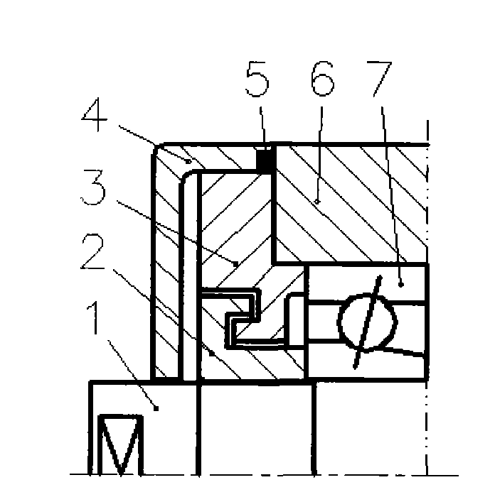
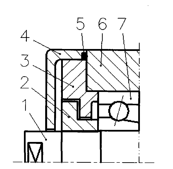
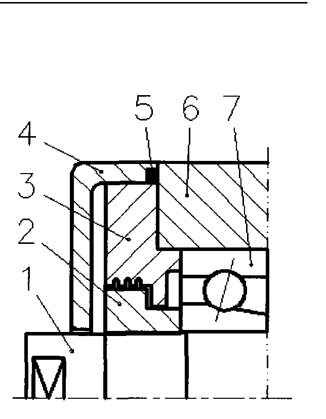
[0019] Combine Figure 4 , The sealing structure design of the electric spindle for oil mist mill of the present invention divides all the components of the front end of the electric spindle into a rotating part and a fixed part. The rotating part includes a shaft (1) and a front nut (2), and the fixed part includes The design points of the front small cover (3), dust cover (4), front bearing seat (6) and newly designed baffle (8) are as follows:

[0020] i. A small clearance fit is used between the rotating part and the fixed part. The standard for small clearance fit is limited to: the radial clearance is controlled within 0.4~0.6mm, and the axial clearance is controlled within 0.5~1mm;

[0021] ii. The axial length of the front nut (2) is lengthened and a water throwing groove and a labyrinth seal structure are designed on it. A convex groove of the labyrinth seal structure is used to mechanically seal the front small cover (3), and the other The elongated convex groove is used ...


PUM


Abstract

A leakproof structure design of an electric main shaft used for an oil mist mill is that a part at front end of the electric main shaft is divided into a revolving part and a motionless part. The revolving part comprises a rotating shaft 1 and a front screw cap 2; the motionless part comprises a front small cover 3, a dust cover 4, a front bearing block 6 and a newly designed baffle 8. Small clearance fit is adopted between the revolving part and the motionless part, with the radial clearance being between 0.4 and 0.6mm and the axial clearance being between 0.5 and 1mm. The axial length of the front screw cap is lengthened and a water splash groove and a labyrinth seal structure are designed along the axial length. A convex groove of the structure is used for mechanically sealing the front small cover, while another lengthened convex groove thereof is used for tightly fixing an inner ring of a bearing 7. The baffle is arranged on the water splash groove and half the width of the baffle can be blocked in the water splash groove but does not revolve with the front screw cap; a water splash recessed groove is designed at the lower end of the half width; and another half width of the baffle closely leans against the head face of the front small cover. The dust cover and the front bearing block adopt an O-shaped sealing ring 5 for sealing. With a drain hole being arranged at the lower end, the sealing ring has good sealing effect and long service life.

Description

Technical field [0001] The invention belongs to the technical field of electric spindle sealing, and particularly relates to a sealing structure design of an electric spindle for oil mist milling. Background technique [0002] The oil mist electric spindle needs to be equipped with an oil mist generator and connected to the electric spindle. The oil mist generator generates a clean pressure oil mist airflow of about 0.3Mpa to enter the bearing part of the electric spindle for lubrication. See the conventional sealing structure of the oil mist electric spindle Figure 1-3 . [0003] When the electric spindle is running normally, the oil mist is continuously supplied to the bearing at a certain pressure, and most of the generated pressure exhaust gas is discharged from the gap between the front small cover and the front nut. The leakage of the exhaust gas also prevents the external generation during the grinding process. Falling abrasive particles, metal powder and cutting fluid at...

Claims


Application Information

Patent Timeline
IPC IPC(8): H02K5/124F16J15/447
Inventor 郭丽娟邱宪国陈长江肖汝峰李彦高飞李玉亭窦怀洛
Owner LUOYANG BEARING SCI & TECH CO LTD
Why Eureka
Try Eureka