
Dipulse interval modulation method of wireless optical communication system

A technology of wireless optical communication and modulation method, applied in the direction of transmission system, electromagnetic wave transmission system, electrical components, etc., to achieve the effect of improving symbol synchronization ability, easy engineering implementation, bandwidth utilization and transmission capacity

Inactive Publication Date: 2009-07-29
程刚
View PDF0 Cites 5 Cited by
  • Summary
  • Abstract
  • Description
  • Claims
  • Application Information

AI Technical Summary

Problems solved by technology

[0006] The purpose of the present invention is to invent a new modulation method. In this method, there is a built-in symbol synchronization capability, which can solve problems such as redundancy or overflow in the buffer during demodulation, and can appropriately shorten the symbol length and improve bandwidth efficiency. and transmission capacity

Method used


Image

  • Dipulse interval modulation method of wireless optical communication system
  • Dipulse interval modulation method of wireless optical communication system
  • Dipulse interval modulation method of wireless optical communication system

Examples


Embodiment

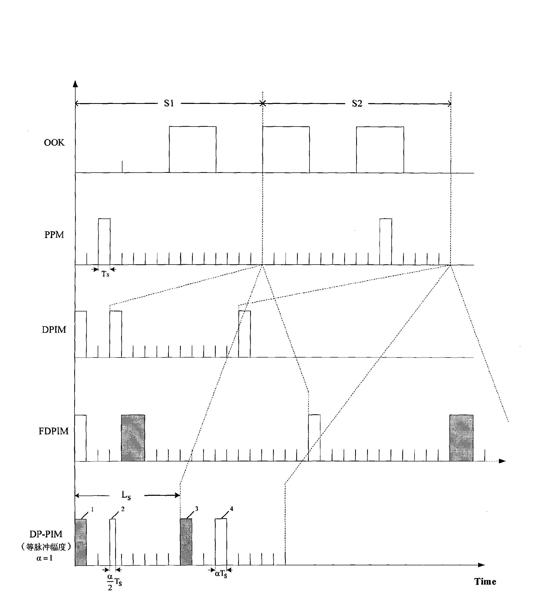
[0038] Design requirements: According to the specific definition of the above-mentioned DP-PIM symbol structure, the amplitudes of the start pulse and the marker pulse are the same, such as figure 1 shown. In the figure, it is assumed that the transmitted information sources are transmitted in groups of M=4 bits. S 1 It means that the transmitted binary array of the first character is 0010, and its corresponding decimal value is k=2. S 2 It means that the binary array passed by the second character is 1010, and its corresponding decimal value is k=10. T S Indicates the slot width. L S Indicates the modulation symbol length.

[0039] Design analysis: According to the design requirements, the symbol structure of DP-PIM needs to reflect the difference in the transmitted information through the change of the width of the marked pulse and the change of the distance between the initial pulse and the marked pulse. The specific implementation process is as follows:

[0040] ①A...


PUM


Abstract

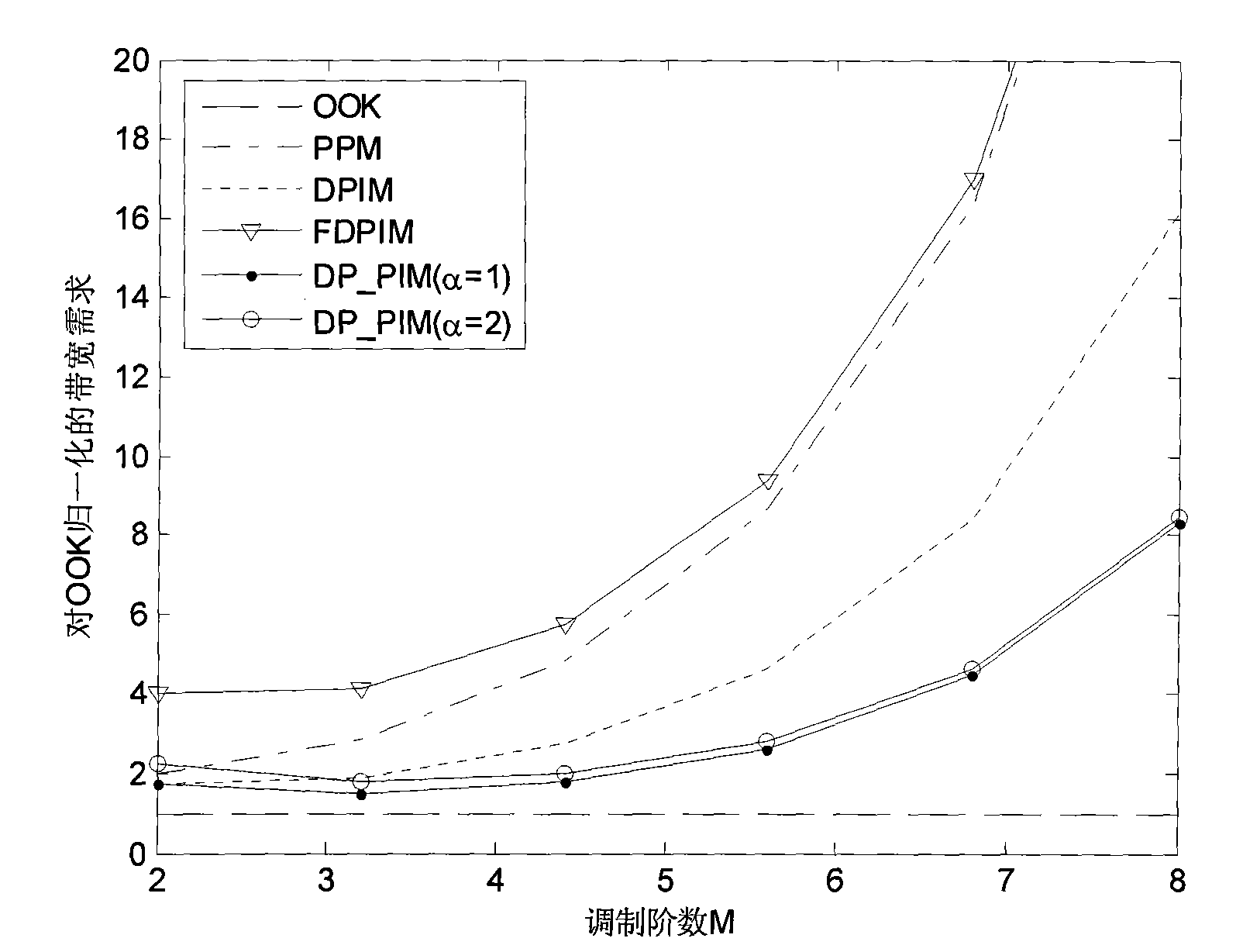
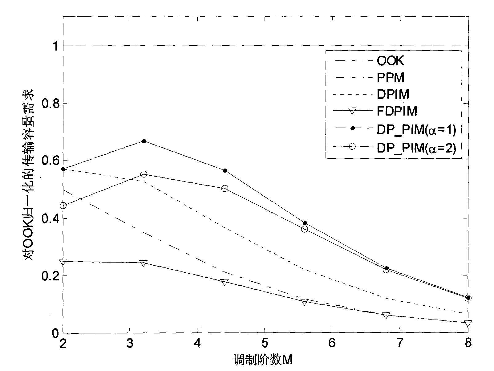
The invention discloses a method for double-pulse interval modulation (DP-PIM) of a wireless optical communication system. The method is based on digital pulse interval modulation. A modulating symbol structure of the invention has fixed symbol length; an initial pulse is fixedly arranged at a first time slot of each symbol, a marker pulse with the alternative pulse width and different spacing of the marker pulse with the initial pulse are utilized to express the transmitted information. The invention not only inherits the advantages brought by the fixed symbol length of PPM, overcomes the defects of easy redundancy and overflow of buffers in DPIM, DH-PIM and DAPIM and the like, but also inherits the advantages brought by the shortened symbol length of the DPIM, the DH-PIM and the DAPIM, reduces the average symbol length by about a half compared with that of PPM and simultaneously also has synchronous capability of built-in symbols. In addition, the invention not only inherits the advantages of FDPIM mode, but also shortens the symbol length by about a half compared with that of the FDPIM, thus obviously improving the bandwidth utilization rate and the transmission capacity.

Description

technical field [0001] The invention relates to a modulation method of a wireless optical communication system, in particular to a modulation method based on a double-pulse interval modulation symbol structure. Background technique [0002] Due to the requirements of human eye safety and portability of mobile devices, the transmitted optical power of wireless optical communication is greatly limited. Under certain conditions of noise and average signal power, to reduce the bit error rate, it is necessary to increase the ratio of signal peak power to average power, and the improvement of power efficiency is usually obtained by increasing the bandwidth requirement. When the shot noise is the main noise, the signal-to-noise ratio is proportional to the area of ​​the photodetector, so in practice, the largest receiving detector should be selected as much as possible. However, the larger the area of ​​the detector, the larger the capacitance, which limits the system bandwidth. ...

Claims


Application Information

Patent Timeline
IPC IPC(8): H04B14/02H04B10/155
Inventor 程刚王红星孙晓明张铁英
Owner 程刚
Learn More