Underframe structure of refrigerated container

A technology for refrigerated containers and underframes, which is applied in packaging, transportation and packaging, and transporting passenger cars. It can solve the problems of low welding efficiency, poor formability, and poor impact resistance, so as to improve production efficiency and product quality, and prevent bubbles. The effect of enhanced delamination ability and enhanced impact resistance

Active Publication Date: 2009-08-05
TAICANG CIMC REEFER LOGISTICS EQUIP CO LTD +2
View PDF0 Cites 4 Cited by
  • Summary
  • Abstract
  • Description
  • Claims
  • Application Information

AI Technical Summary

Problems solved by technology

[0003] The problem to be solved by the present invention is to overcome the following disadvantages in the corrugated underframe structure of the existing refrigerated container: (1) The welding of the corrugated sub-floor and the bottom side beam is all manual welding, which has low welding efficiency and poor formability (2) It is difficult to carry out paint construction on the corrugated sub-floor, which is likely to cause large differences in paint film thickness at the peaks and troughs, and serious waste; (3) The corrugated sub-floor will be affected by trailer locks and stones on uneven ground. It is damaged due to collision, and the corrugated board is difficult to repair; (4) The strength of the chassis mainly depends on the polyurethane foam for bearing, and the impact resistance is poor, and the foam is easy to delaminate

Method used


Image

  • Underframe structure of refrigerated container
  • Underframe structure of refrigerated container
  • Underframe structure of refrigerated container

Examples


Embodiment Construction

[0023] The present invention will be further described below through specific embodiments with reference to the accompanying drawings, the purpose of which is to facilitate the understanding of the present invention for illustration purposes and not to limit the present invention.

[0024] The idea of ​​the present invention is to improve the structural strength of the underframe of the refrigerated container by improving the underframe structure of the refrigerated container, so that the underframe of the refrigerated container is easy to process and manufacture.

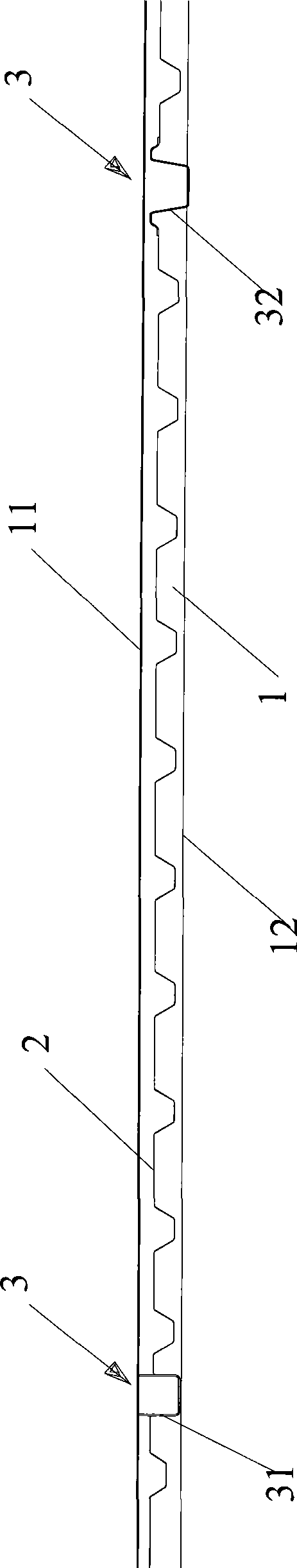
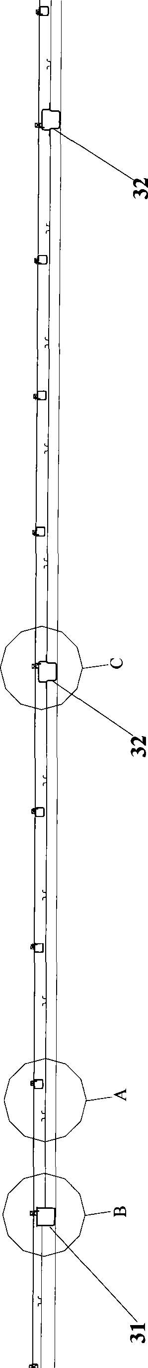
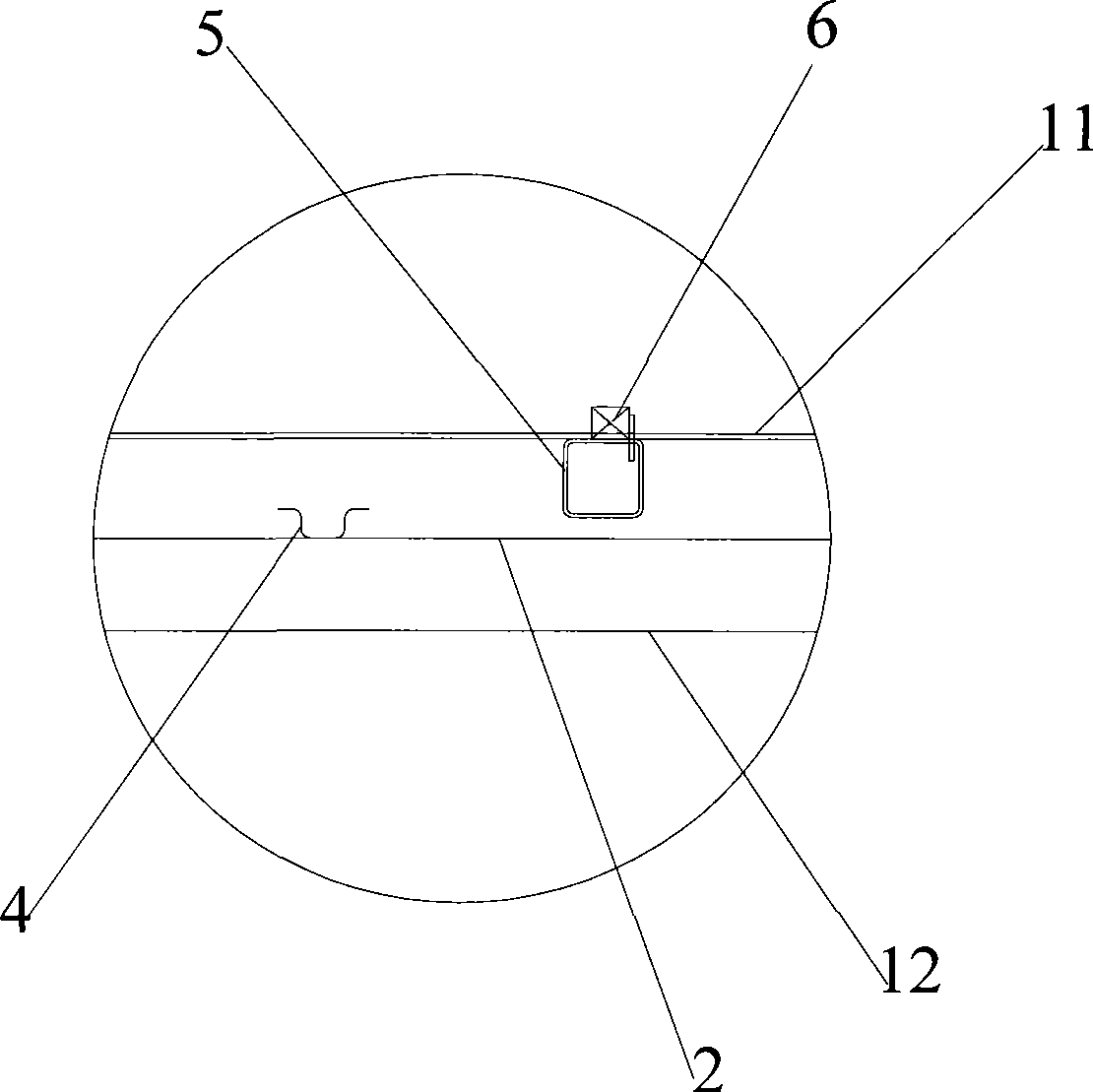
[0025] Embodiments of the present invention will now be described in detail with reference to the drawings. figure 2 It is a partial structural schematic diagram of the longitudinal section of the bottom frame of the refrigerated container of the present invention, image 3 , Figure 4 and Figure 5 respectively figure 2 Schematic diagram of the enlarged structure of parts A, B and C in the middle, Figure 6 ...


PUM


Abstract

The invention provides a chassis structure for a refrigerating container, which comprises two bottom side beams which are longitudinally arrayed, an auxiliary floor which is arranged between the two bottom side beams and a bottom beam which is arrayed transversely, wherein both ends of the bottom beam are connected with a left bottom side beam and a right bottom side beam respectively. The chassis structure of the refrigerating container is characterized in that the auxiliary floor is a flat plate; the chassis structure also comprises a plurality of reinforcing ribs which are arrayed transversely with a preset space and welded to the upper side of the auxiliary floor, and both ends of each reinforcing rib are connected with the left bottom side beam and the right bottom side beam respectively; and the bottom beam comprises a main bottom beam and two auxiliary bottom beams, wherein lower edges of the main bottom beam and the auxiliary bottom beams are parallel to that of the bottom side beams, and upper edges of the main bottom beam and the auxiliary bottom beams are higher than a plane formed by the auxiliary floor. The chassis structure reduces the damage probability of the auxiliary floor, improves the repairing efficiency, reduces the cost, can achieve the automatic welding and automatic painting, and improve the production efficiency and the product quality, so that the structure strength, the shock resistant capability and the capability of preventing foam from layering of a base plate are improved.

Description

technical field [0001] The invention relates to an assembly of a refrigerated container, in particular to an underframe structure of the refrigerated container. Background technique [0002] The underframe structure, foam layer and T floor of the refrigerated container together constitute the load-bearing structure of the goods in the refrigerated container. The underframe part of the refrigerated container is mainly composed of (i) two bottom side beams arranged longitudinally, (ii) a plurality of bottom beams arranged horizontally and (iii) an auxiliary floor; a T floor is set above the underframe part ; A closed space is formed between the T floor and the auxiliary floor, and this space is the foaming area. The sub-floor of the existing underframe is generally formed by overlapping or splicing (welding or bonding) multiple corrugated sub-floors to form a whole sub-floor. Bottom side beams and 2 to 3 bottom beams are welded together. Such as figure 1 As shown, which sh...

Claims


Application Information

Patent Timeline
Patent Type & Authority Applications(China)
IPC IPC(8): B65D90/02B65D88/74
Inventor 宋卫国彭继红侯丰收
Owner TAICANG CIMC REEFER LOGISTICS EQUIP CO LTD
Why Eureka
Try Eureka