Thermoelectric module
A thermoelectric module and thermoelectric element technology, which is applied to thermoelectric device parts, circuits, electrical components, etc., can solve problems such as potential difference and short circuit, and achieve the effect of suppressing deterioration
- Summary
- Abstract
- Description
- Claims
- Application Information
AI Technical Summary
Problems solved by technology
Method used
Image

Examples
no. 1 Embodiment approach
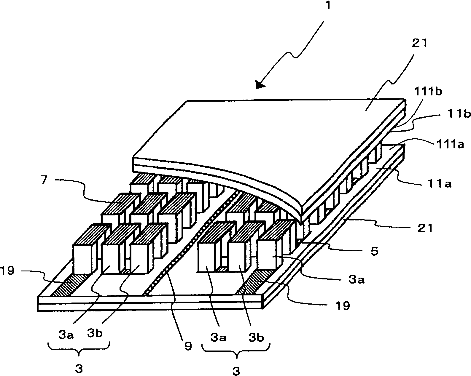
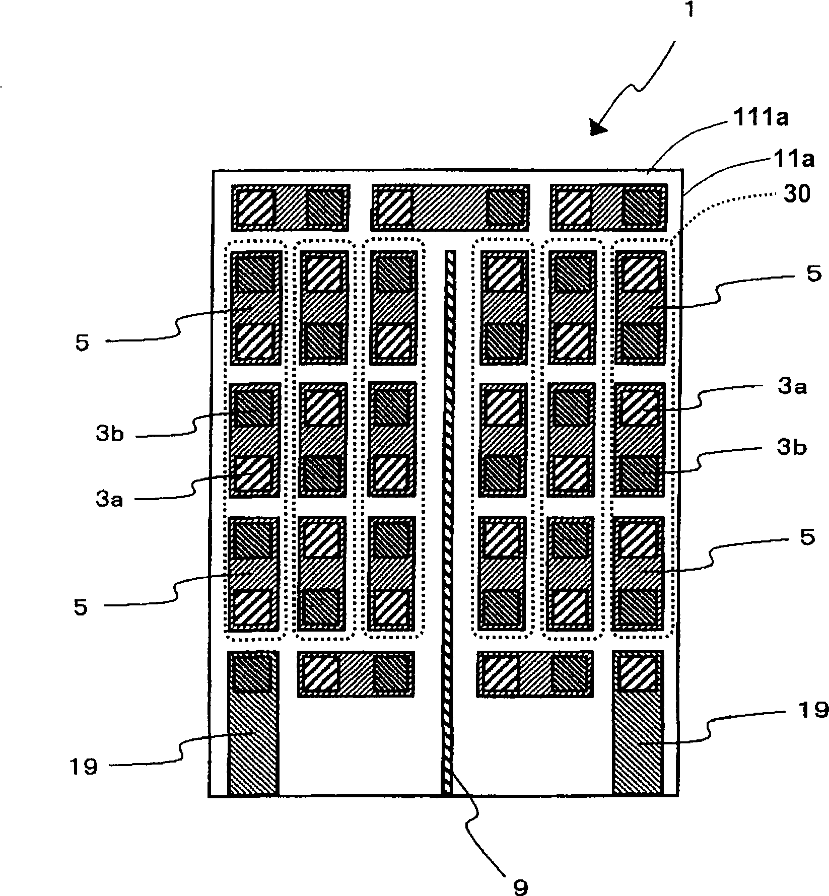
[0061] figure 1 as well as figure 2 The thermoelectric module according to the first embodiment of the present invention is shown.
[0062] The thermoelectric module 1 of this embodiment includes: a plurality of thermoelectric elements 3 sandwiched by a pair of substrates 11a, 11b (first substrate 11a, second substrate 11b); and a plurality of rectangular electrodes 5, 7 (first electrode 5, the second electrode 7), which are respectively formed on the surfaces (first surface, second surface) of a pair of substrates 11a, 11b on the thermoelectric element 3 side, and electrically connect a plurality of thermoelectric elements 3 in series; a plurality of electrodes 5 and 7 include a plurality of columns 30 arranged in the longitudinal direction, and a ground electrode 9 is provided on the surface of the substrate 11a, 11b between adjacent columns 30, and the ground electrode 9 is located on two adjacent columns 30. between columns.
[0063] That is, the thermoelectric module ...
no. 2 Embodiment approach
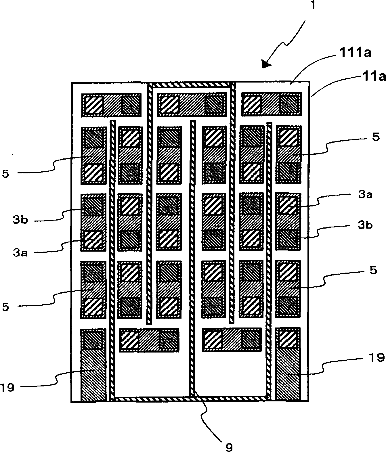
[0105] image 3 and Figure 4 A thermoelectric module according to a second embodiment of the present invention is shown. In addition, in this embodiment, only the point which differs from the said 1st Embodiment is demonstrated, the same reference numeral is used for the same component, and the overlapping description is abbreviate|omitted.
[0106] In the thermoelectric module 1 of the present embodiment, the ground electrode 9 is provided at a plurality of positions parallel to the circuit of the thermoelectric module 1 . Therefore, compared with the first embodiment, the occurrence of electrical short circuit can be further suppressed.
[0107] especially if Figure 4 As shown, it is preferable to provide the ground electrode 9 between all the adjacent first electrodes 5 . Thus, with image 3 Compared with the illustrated embodiment, the occurrence of electrical short circuit can be further suppressed.
no. 3 Embodiment approach
[0109] Figure 5 and Image 6 A thermoelectric module according to a third embodiment of the present invention is shown. In addition, in this embodiment, only the difference from the above-mentioned first embodiment will be described, and the same reference numerals will be used for the same components, and overlapping descriptions will be omitted.
[0110] The thermoelectric module of this embodiment includes a thermistor 13 connected to the ground electrode 9 in addition to that described in the first embodiment. Thereby, the ground electrode 9 can be used as a part of the circuit 23 of the thermistor 13 , and it is possible to suppress a decrease in measurement accuracy of the thermistor 13 even when a leakage current occurs.
[0111] The thermistor 13 may be disposed on at least one of the first surface 111a and the second surface 111b. At this time, the temperature of the thermoelectric module 1 can be controlled with high precision by using the thermistor 13 .
[011...
PUM
 Abstract
Description
Claims
Application Information
 - R&D
- Intellectual Property
- Life Sciences
- Materials
- Tech Scout
- Unparalleled Data Quality
- Higher Quality Content
- 60% Fewer Hallucinations
Browse by: Latest US Patents, China's latest patents, Technical Efficacy Thesaurus, Application Domain, Technology Topic, Popular Technical Reports.
© 2025 PatSnap. All rights reserved.Legal|Privacy policy|Modern Slavery Act Transparency Statement|Sitemap|About US| Contact US: help@patsnap.com