
Method of forming injection hole for injector

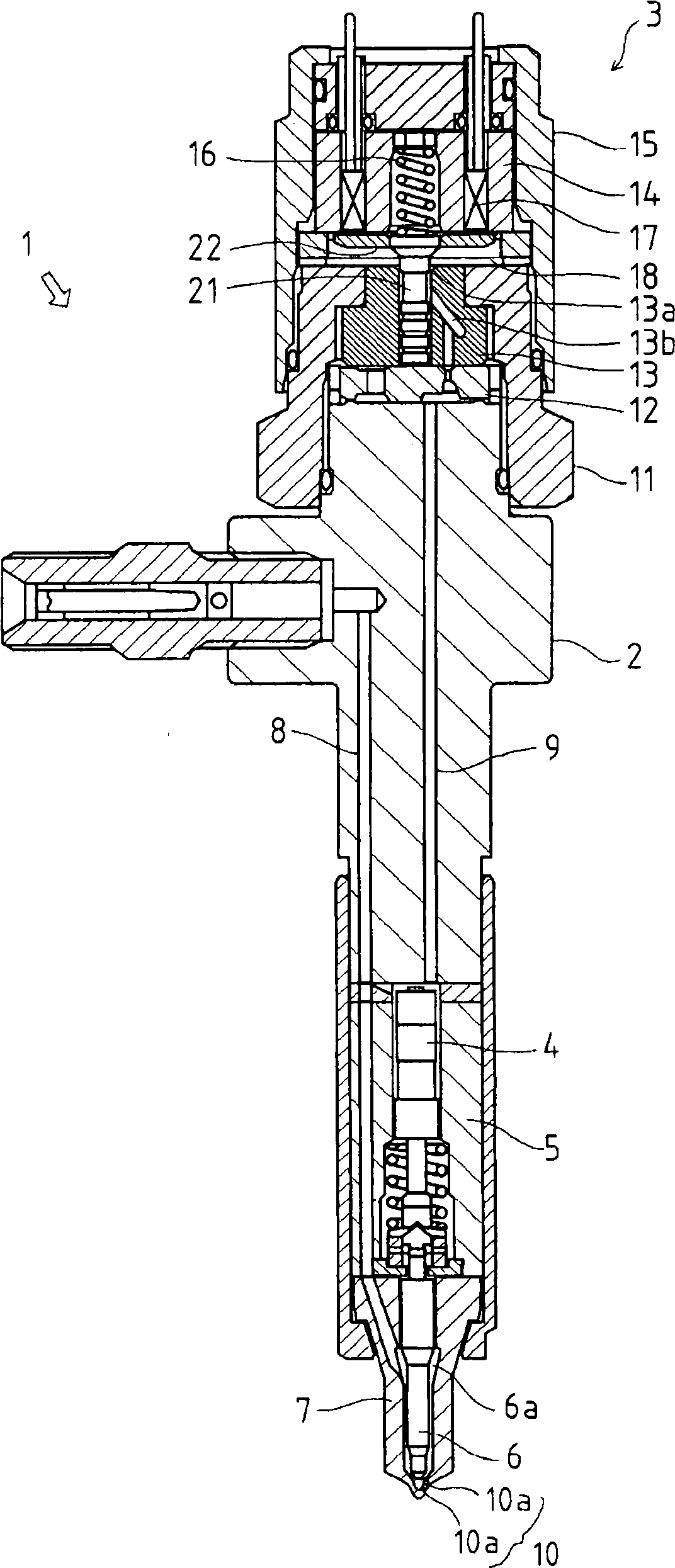
An injector and piercing technology, applied in the direction of fuel injection device, special fuel injection device, mechanical equipment, etc., can solve the problems of the influence of exhaust gas properties, difficult to meet, uneven exhaust gas properties, etc., to reduce processing tolerances, Reduced uneven, stable performance effects

Inactive Publication Date: 2009-08-05
YANMAR CO LTD +1
View PDF1 Cites 0 Cited by
  • Summary
  • Abstract
  • Description
  • Claims
  • Application Information

AI Technical Summary

Problems solved by technology

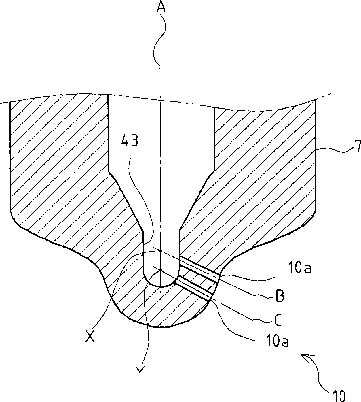
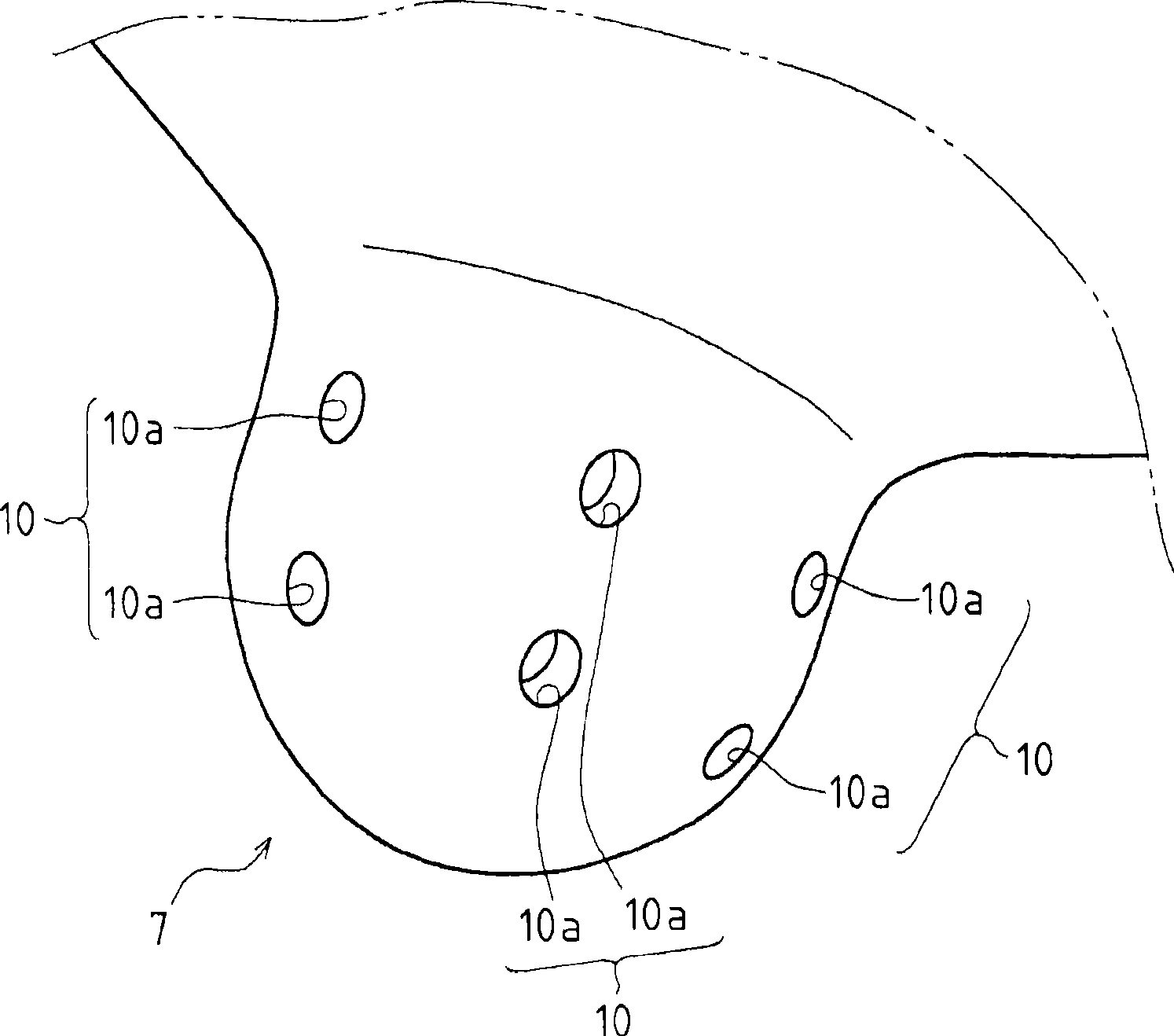
[0006] However, it can be seen from experimental results that, in an injector having a group of injection holes, processing unevenness such as the piercing position of the injection holes, the relative position and relative angle of each injection hole, or twisting in the circumferential direction will affect the quality of the exhaust gas. have a direct impact
[0007] Therefore, in an injector with a group of injection holes, it is required to suppress processing unevenness such as the piercing position of the injection holes, the relative position and relative angle of each injection hole, or the distortion in the circumferential direction to ensure high processing accuracy. At present, because the nozzle holes are drilled by electric discharge machining on the curved surface of an approximate sphere, it is difficult to meet the specified shape tolerance and ensure the machining accuracy in the actual production process.
As a result, the distribution uniformity of the atomized fuel decreases, resulting in unevenness in the properties of the exhaust gas.
Moreover, it can be seen from this problem that it is difficult to realize the practicality of injectors with group injection holes.

Method used


Image

  • Method of forming injection hole for injector
  • Method of forming injection hole for injector
  • Method of forming injection hole for injector

Examples


Embodiment 1

[0055] First, if Figure 4 As shown, the configuration is as follows: a concave portion 10b is provided in the piercing portion of the group injection holes 10 (injection holes 10a, 10a), a flat portion 10c is formed at the bottom of the concave portion 10b, and the group injection holes 10 are pierced on the flat portion 10c.

[0056] The plane part 10c is formed with a plane perpendicular to the axis of the injection hole 10a formed therethrough, and can be easily formed by machining such as cutting or forging. In addition, dimensional tolerances such as relative positions and angles of the recessed portions 10b, 10b . . . and plane surfaces 10c, 10c .

[0057] Therefore, the injection holes 10a, 10a can be drilled in the flat surface portion 10c where the dimensional tolerance is ensured, thereby improving the machining accuracy.

[0058] In addition, in this embodiment, an example is shown in which the group injection holes 10 (injection holes 10a, 10a) are perforated on ...

Embodiment 2

[0060] Below, such as Figure 5 As shown, the configuration is such that a planar portion 10d is provided at the pierced portion of the group injection holes 10 (injection holes 10a, 10a), and the group injection holes 10 are formed on the planar portion 10d.

[0061] The plane part 10d is formed with a plane perpendicular to the axis of the injection hole 10a formed therethrough, and can be easily formed by machining such as cutting or forging. In addition, dimensional tolerances such as relative positions and angles of the planar portions 10d, 10d, . . . can be secured relatively easily by machining.

[0062] Therefore, the injection holes 10a, 10a can be drilled through the flat surface portion 10d where the dimensional tolerance is ensured, so that the machining accuracy can be improved.

[0063] In addition, in this embodiment, an example is shown in which the group injection holes 10 (injection holes 10a, 10a) are perforated by machining (for example, drilling) on ​​eac...


PUM


Abstract

In a method for boring injection holes of an injector 1 having a plurality of intersections between an axis line of the injector 1 and the axes of the injection holes 10a bored in the injector 1, or so-called a group of injection holes 10, flat sections 10c, 10d, which are perpendicular to the injection holes 10a and include apertures of the injection holes 10a, are formed on boring portions of injection holes 10a. The boring portions are provided with recessed portions 10b and the recessed portions 10b are formed at the bottom thereof with flat sections 10c. Alternatively, the flat sections 10c, 10d are formed by cutting the boring portions, or by forging them.

Description

technical field [0001] The present invention relates to the technique of an engine injector having a common rail type fuel injection device, and more specifically, to a method of piercing a nozzle hole of an injector having a so-called group nozzle hole. Background technique [0002] Conventionally, a common rail type fuel injection device included in a diesel engine is well known, and a specific structure of an injector that injects fuel supplied from the common rail is also well known. [0003] In addition, injectors with so-called groups of orifices are known, in which there are several points of intersection of the injector axis and the axis of the orifices formed in the nozzle body of the injector. [0004] Compared with an injector without a group of nozzle holes having the same amount of atomization, the injector with a group of nozzle holes can reduce the diameter of the nozzle hole. It can be seen that if the injector with group injection holes is used, compared wi...

Claims


Application Information

Patent Timeline
Patent Type & Authority Applications(China)
IPC IPC(8): F02M61/18
CPCF02M61/18F02M2200/8053F02M2200/8069F02M61/188F02M61/168F02M61/182F02M61/1893Y10T29/49298Y10T408/03
Inventor 高桥岳志高畑辉光鹈饲智美朝井豪清水功治河边隆夫篠原幸弘津田知是
Owner YANMAR CO LTD
Learn More