Shaft seal device

A technology for shaft seals and sealing parts, which is applied to engine seals, engine components, mechanical equipment, etc. It can solve problems such as difficult removal, rusting of the metal ring 210, leakage of sealed fluid, etc., and achieves simple assembly structure and small elastic deformation , the effect of preventing adhesion

Active Publication Date: 2009-08-05
EAGLE INDS
View PDF3 Cites 10 Cited by
  • Summary
  • Abstract
  • Description
  • Claims
  • Application Information

AI Technical Summary

Problems solved by technology

Since the flange portion 210A must press or machine the outer peripheral surface of the thin-walled metal ring 210, the processing is difficult.
Therefore, making the sealing device 200 unsuitable for mass production
[0007] In addition, since the metal ring 210 is embedded in the installation hole of the cover body 260, the sealed fluid may leak from the joint between the metal ring 210 and the cover body 260.
Furthermore, the accumulation of sealed fluid in the fitting ring between the metal ring 210 and the cover body 260 will cause the metal ring 210 to rust.
In addition, when the sealing device 200 is taken out from the installation hole of the cover body 260 in order to repair the sealing device 200 etc., it becomes difficult to take out the metal ring 210 of the sealing device 200 which is pressed in due to the combination of the two parts.
In addition, when the fitting surface of the ferrule 210 is rusted, it is more difficult to take it out from the cover body 260 due to strong adhesion due to the rust.

Method used


Image

  • Shaft seal device
  • Shaft seal device
  • Shaft seal device

Examples


Embodiment 1

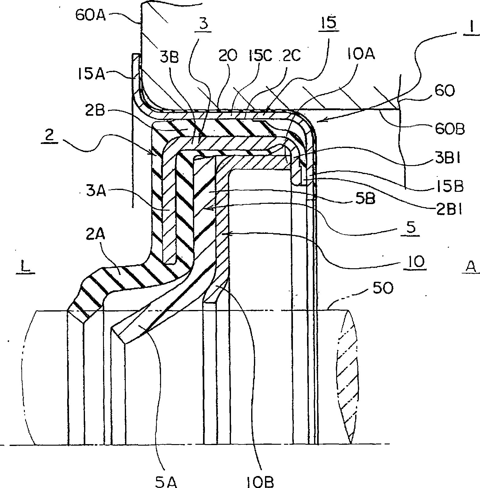
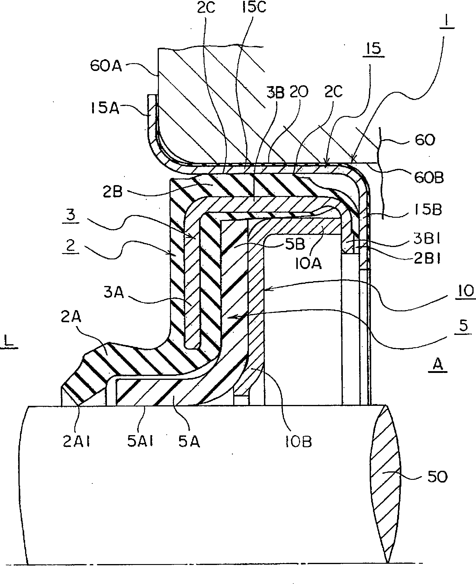
[0056] First, Embodiment 1 of the shaft sealing device 1 of the present invention will be described. figure 1 It is a sectional view of one side of the shaft sealing device 1 . figure 2 for will figure 1 A cross-sectional view of one side of the state where the shaft sealing device is inserted into the rotary shaft 50 . refer to the figure 1 and figure 2 Be explained. The rotary shaft 50 is attached to a hole forming surface (hereinafter referred to as a hole) 60B provided on the cover 60 . The sealed fluid existing in the equipment interior L between the hole 60B and the rotary shaft 50 is sealed by the shaft sealing device 1 . The fluid to be sealed is, for example, a coolant or the like with temperature and pressure. In a specific example, a cooling fluid or the like for cooling a radiator or the like is sealed.

[0057] The first sealing part 2 is formed with a cylindrical fitting part 2B, a first sealing lip 2A extending radially inward at one end of the fitti...

Embodiment 2

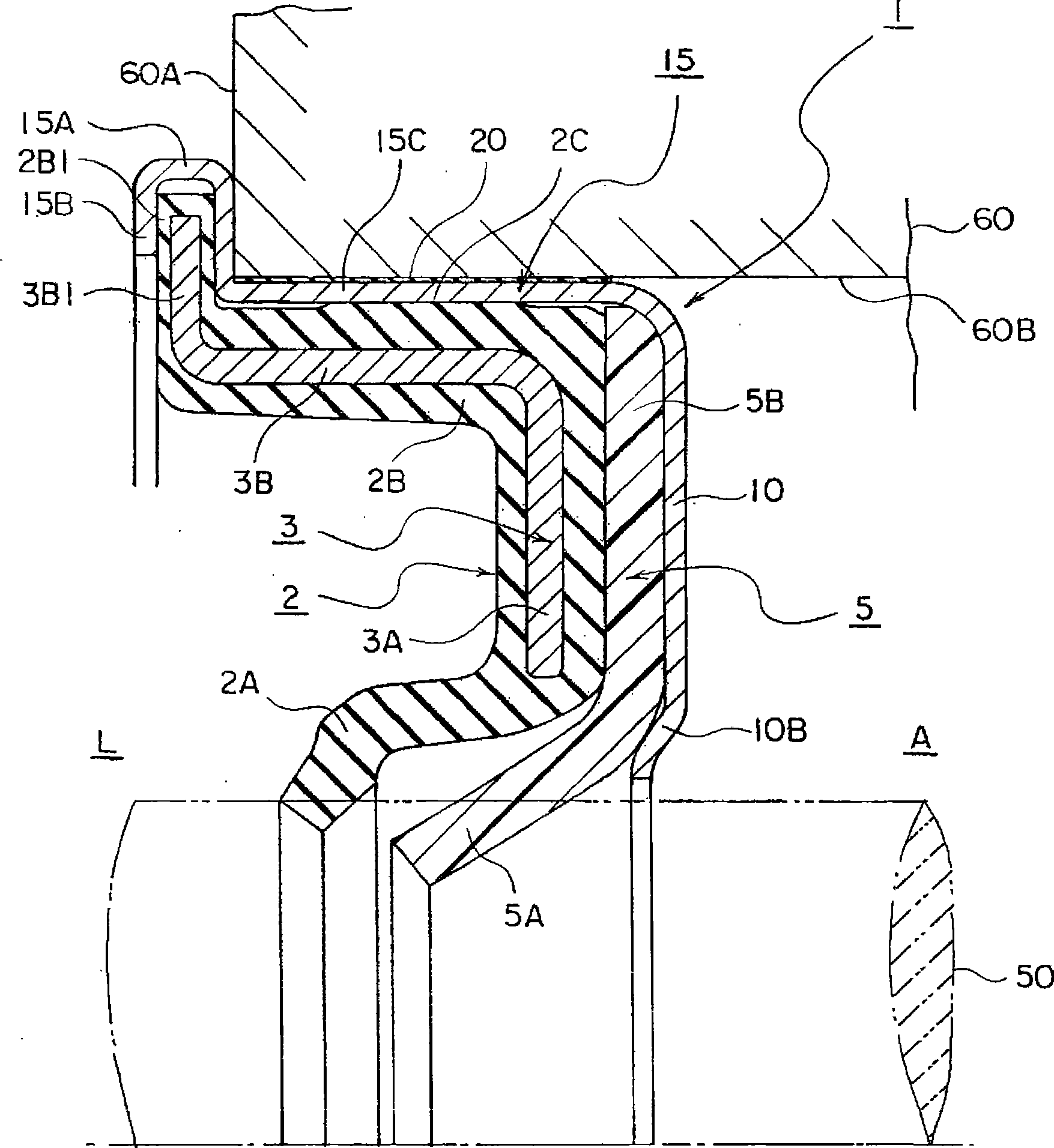
[0065] Hereinafter, the shaft sealing device 1 according to the second embodiment of the present invention will be described. image 3 It is a sectional view of one side of the shaft sealing device 1 of the second embodiment. exist image 3 In this case, the hole 60B of the seal cover 60 is not provided with a stepped positioning portion for positioning and fixing the shaft seal device 1 in the axial direction. In this shaft seal device 1, with figure 1 The difference is that the connecting parts 2B1 and 3B1 of the first sealing part 2 are compared to figure 1 The connecting parts 2B1 and 3B1 of the first sealing part 2 are arranged on the side of the first engaging part 15A. Furthermore, the second connecting portion 3B1 is formed in a flange shape from the cylindrical portion 3B of the reinforcement ring 3 toward the same direction as the first engaging portion 15A. The connection parts 2B1 and 3B1 of the first seal part 2 are formed by the second connection part 3B1 o...

Embodiment 3

[0069] Hereinafter, the shaft sealing device 1 according to the third embodiment of the present invention will be described. Figure 4 It is a sectional view of one side of the shaft sealing device 1 of the third embodiment. exist Figure 4In this case, the step positioning portion for fixing the shaft seal device 1 in the axial direction is not provided in the hole 60B of the seal cover 60 . In this shaft seal device 1, with figure 1 The difference is a modified embodiment in which the snap ring (also referred to as snap plate) 15 and the reinforcement ring 3 are integrated. The reinforcement ring 3 is with figure 1 The reinforcement rings 3 are roughly the same shape. And, snap ring 15 and Figure 4 The reinforcement ring 3 shown in combination, with figure 1 A portion corresponding to the fitting portion 15C of the reinforcing ring 3 also serves as the cylindrical portion 3B of the reinforcing ring 3 . That is, the snap ring 15 is provided with a first snap portio...


PUM


Abstract

A shaft sealing device having a first seal section, a second seal section, a first back plate, and an engagement ring. The first sealing section has a fitting section fitted in a seal housing, a first seal lip whose inner peripheral surface is sealingly fitted on the outer peripheral surface of a shaft to seal fluid, and a reinforcement ring having reinforcement section for holding the first seal lip and also having a tube section and connection section that are integrally joined to the fitting section. The second seal section is made of resin, placed on the opposite side of the first seal section from the sealed fluid, and has the inner peripheral surface sealingly fitted on the shaft. The first back plate is supported by the reinforcement ring or engagement ring for holding a support section of the second seal section. The engagement ring has a fitting section fitted to a hole forming surface of the seal housing, has a first engagement section engaging with an end face of the seal housing, and has a second engagement section for causing the first engagement section to support the reinforcement ring. The device has a seal between the surface of the engagement ring and the hole forming surface, and the seal has a smaller radial thickness than the reinforcement ring or the engagement ring.

Description

technical field [0001] The present invention relates to a shaft seal device for sealingly blocking a gap between a rotary shaft mounted on a hole forming surface of a cover and the hole forming surface by a sealing fluid. In particular, it relates to a shaft seal device in which a sealing portion made of a rubber-like elastic material and a sealing portion made of a resin material are arranged in parallel to improve pressure resistance against a fluid to be sealed and facilitate installation. Background technique [0002] As related technology of the shaft seal device of the present invention, there is a shaft seal device similar to Patent Document 1 described below. This shaft sealing device is mounted in a bearing mounting hole around a rotating shaft through which a wall of a pump casing penetrates, and seals a to-be-sealed fluid. In addition, the sealed fluid is, for example, cooling water pumped by a pump to cool the radiator. [0003] The shaft sealing device 100 is ...

Claims


Application Information

Patent Timeline
Patent Type & Authority Applications(China)
IPC IPC(8): F16J15/32
CPCF16J15/3228F16J15/12F16J15/32
Inventor 真田雅光
Owner EAGLE INDS
Why Eureka
Try Eureka