Rotary table type machine for automatic continuous production of balls

A turntable type, ball machine technology, applied in the field of cooking machinery, can solve problems such as noise productivity

Inactive Publication Date: 2009-08-12
谭云霞
View PDF0 Cites 3 Cited by
  • Summary
  • Abstract
  • Description
  • Claims
  • Application Information

AI Technical Summary

Problems solved by technology

[0003] The purpose of the present invention is to overcome the noise and productivity problems of the original model, and propose this proposal——rotary disc automatic continuous production ball machine

Method used


Image

  • Rotary table type machine for automatic continuous production of balls
  • Rotary table type machine for automatic continuous production of balls
  • Rotary table type machine for automatic continuous production of balls

Examples


Embodiment 1

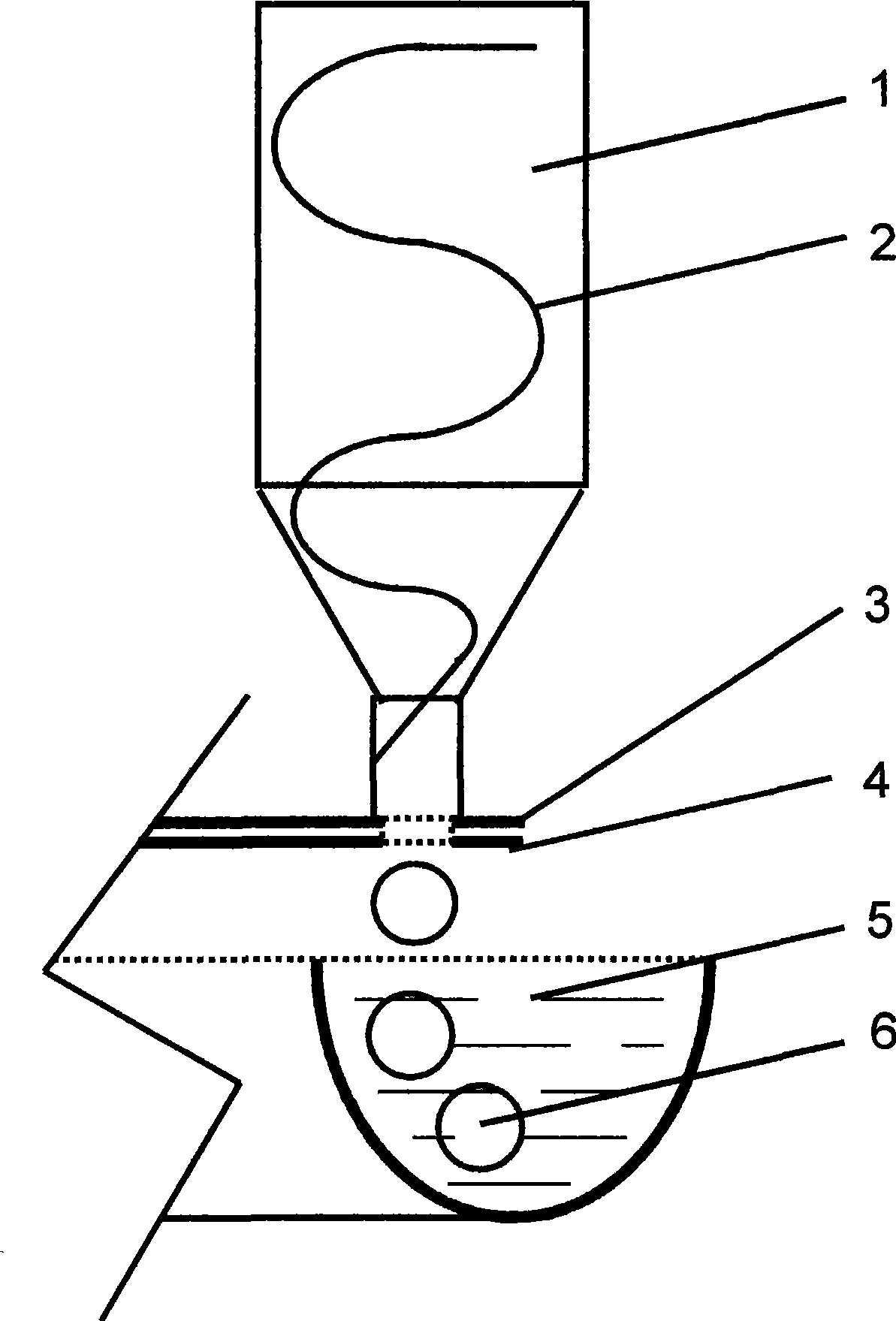
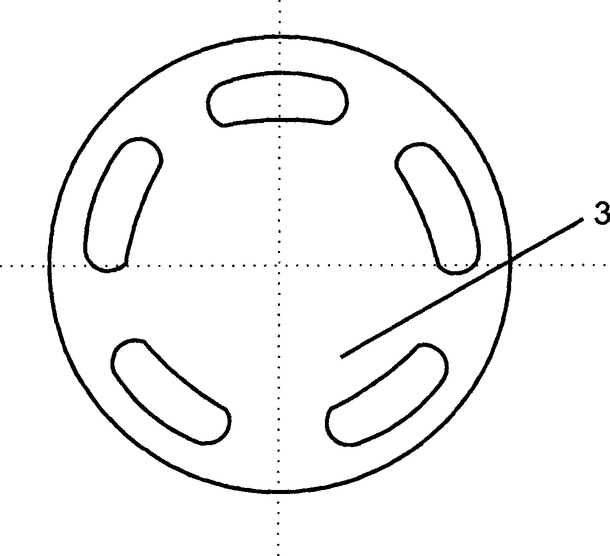
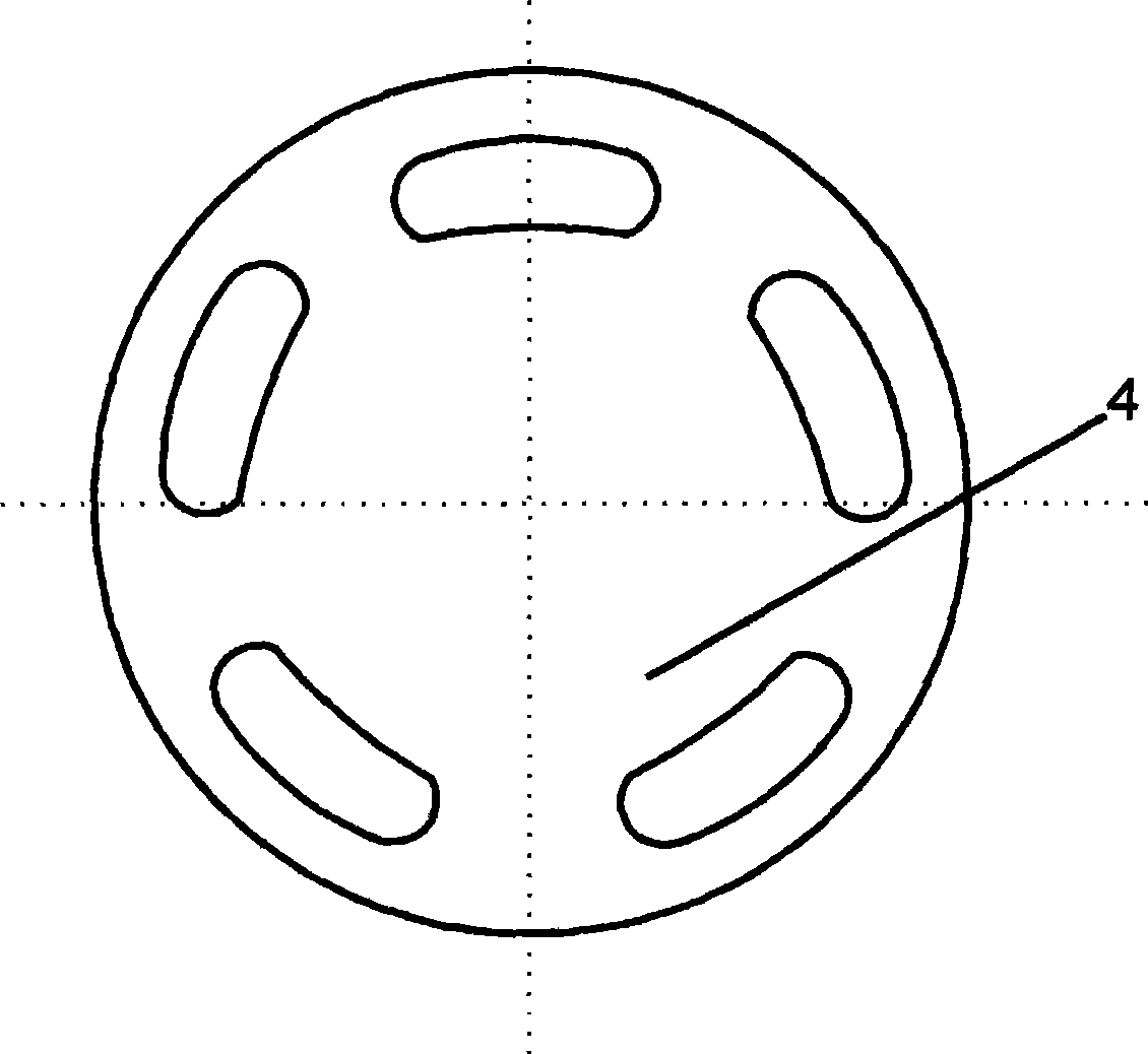
[0015] exist figure 1 , figure 2 and image 3 In the schematic diagram of the rotary table type automatic continuous production meatball machine shown, the present invention is to overcome the problems of high noise and vibration of the original machine and low productivity. It is composed of a raw material cylinder 1, a conveyor 2, a first filling plate 3 and a second filling plate 4, and each of the first filling plate 3 and the second filling plate 4 has a number corresponding to the number of units. Two circular arc long holes with the same specification, their distribution diameters are the same, driven by a motor, the rotation directions of the two discs are opposite, and the direction of rotation of the two discs is reversed with a 1:1 gear in the transmission chain, and the arcs on the two filling plates When the long holes intersect, the center is aligned with the discharge opening of the raw material cylinder 1 .

[0016] When working, put the stirred meat stuffi...

Embodiment 2

[0020] At the outlet of the bottom of the raw material cylinder, the same upper and lower two large disc-type filling plates as in the first embodiment, the difference from the first embodiment is that the upper and lower two large disc-type large filling plates are not one forward and the other Reverse asynchronous rotation, but do the reciprocating motion that rotates in the opposite direction until the distance of a ball is stopped, and then turns back to the distance of a ball and then stops. There is a hole on each plate, when the holes on the two discharge plates When the timing is relative to the discharge port of the bucket, the stuffed meat passes through, and the discharge stops when the two holes miss, and the stuffed meat extruded is formed into balls 6 in the hot water 5 below.

Embodiment 3

[0022] At the outlet at the bottom of the raw material cylinder 1, there are two large disc-type large filling plates up and down the same as in embodiment one. The difference from embodiment one and implementation two is that the two large disc-type large filling plates up and down are not a front To the other reverse asynchronous rotation, but the lower large disc type filling plate 4 is stationary, only the upper large disc type filling plate 3 rotates circularly or only has the distance of a meatball to reciprocate.


PUM


Abstract

The invention provides a rotary meat ball making device capable of automatically continuously producing meat balls, characterized in that: the meat ball making device is driven by a motor and the rotation directions of the two rotary disks are opposite and 1:1 gear commutation is used for in a transmission chain. When two arc brakes of two stuffing feeding plates meet at the discharging gate under the bucket, the meat stuffing immediately is discharged into hot water and then shaped into meat balls. Two large stuffing feeding plates of each machine set are changed into two large round disk, wherein one round disk is driven by the motor and another one is driven after 1:1 gear reversing and the rotation principle is same to the rotation principle of each machine set, a plurality of arc long holes are opened on each large stuffing discharging plate and the arc long holes are in up and down correspondence and a plurality of raw-material cylinder discharge-gates are corresponding with the arc long holes. The production efficiency is increased and the noise is reduced.

Description

technical field [0001] The invention belongs to the category of cooking machinery. It specifically relates to a rotary table type automatic continuous production nine-piece machine device. Background technique [0002] In the prior art, there is a meatball machine that puts the stirred meat stuffing in the material barrel and conveys it downwards by a screw conveyor. At the outlet at the bottom of the barrel, there are two upper and lower discharge plates that reciprocate in opposite directions. Each plate has a hole. When the holes on the two discharge plates are aligned with the outlet of the barrel, the meat stuffing will pass through. When the two holes miss the discharge, the material will stop, and the extruded meat stuffing will be formed in the hot water below. . Its advantages are simple structure and reliable operation. The disadvantage is that the reciprocating motion has a lot of impact noise and vibration, and it can only produce one ball at a time, so the pro...

Claims


Application Information

Patent Timeline
IPC IPC(8): A23P1/12A23P30/20
Inventor 谭云霞
Owner 谭云霞
Why Eureka
Try Eureka