Steel ball sowing apparatus
A technology of steel balls and buffer buckets, applied in the field of power engineering
Inactive Publication Date: 2010-09-15
XI AN JIAOTONG UNIV +1
View PDF0 Cites 0 Cited by
- Summary
- Abstract
- Description
- Claims
- Application Information
AI Technical Summary
Problems solved by technology
In the case of uneven sowing of steel balls, it is often necessary to run the steel ball cleaning system frequently, which increases the unreliability of the system
In addition, steel balls are easily rusted and clumped when circulating in the cleaning system and temporarily stored, especially in the flue gas containing H2O, SO2 and other gases , the ash content of complex components
Once the steel balls are agglomerated, it is difficult to eliminate, which will block the steel ball spreading nozzle and steel ball conduit, making maintenance difficult
Method used
View moreImage
Smart ImageViewing Examples
Examples
Embodiment 2
Login to View More PUM
 Abstract
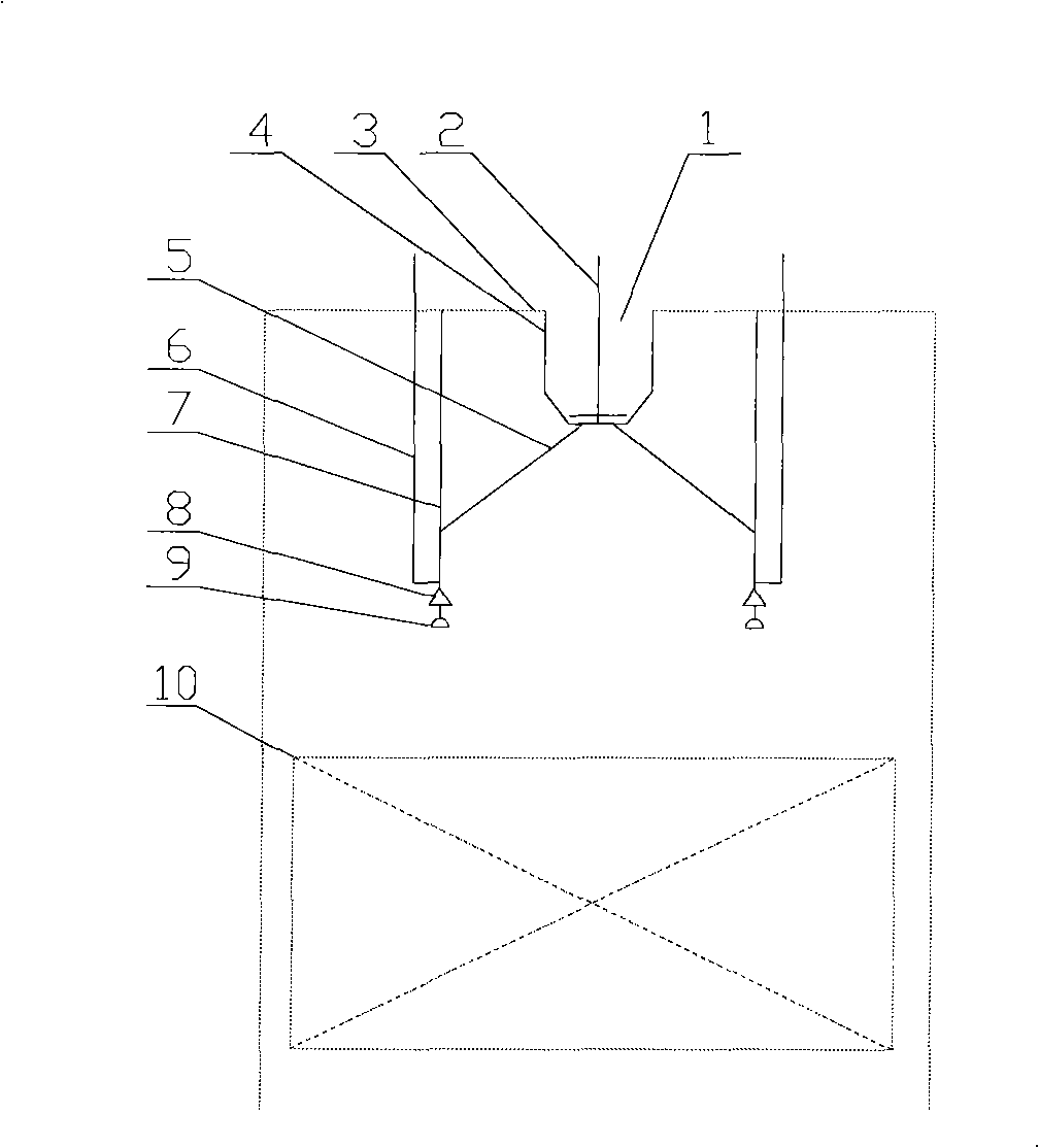
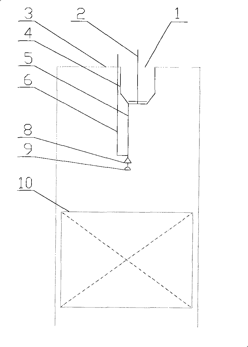
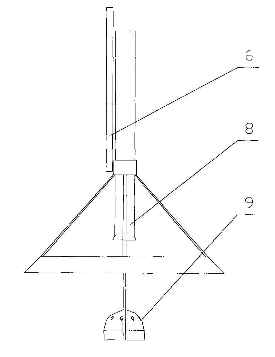
The invention discloses a steel ball spreading device for steel ball ash removal of a boiler. The device comprises a buffer hopper, a distribution adjusting rod, a guide pipe, an adjusting rod of a rebounding machine, a steel ball nozzle, and a steel ball rebounding machine. The prior steel ball spreading device has the common defects, namely the steel balls are not evenly distributed on the cross section of a hearth, the density distribution cannot be adjusted, the steel balls are easily rusted and agglomerated and the like, so that the ash deposit on the heating surface cannot be completelyand effectively removed, the big ash deposit is agglomerated locally, and the reliability of a system is not high. The device is characterized in that: a set of steel ball spreading device is designed aiming at the steel ball ash removal mode of the boiler, so that the device can ensure the reasonable density distribution of steel ball spreading and the adjustability of the density distribution of the steel ball spreading; moreover, the device creates conditions for realizing the automatic control of the highly efficient steel ball ash removal.
Description
technical field [0001] The invention belongs to a dust removal device in the technical field of power engineering, and in particular relates to a steel ball spreading device used in a boiler steel ball dust removal system. Background technique [0002] Other boiler soot cleaning methods, such as: compressed air soot blowing, mechanical vibration, steam soot blowing, are often not effective or not effective for cohesive soot deposits, firm soot deposits, and ash deposits that will react chemically with water. Applicable, and the steel ball cleaning method has relative advantages. [0003] The steel ball spreading device is an important part of the steel ball dust cleaning system. Most of the existing systems are based on the principle of sowing by steel balls rebounding, but there are also some common shortcomings, such as: steel balls are unevenly distributed on the cross-section of the furnace after rebounding, and the density distribution of steel balls cannot be controll...
Claims
Login to View More Application Information
Patent Timeline
 Patent Type & Authority Patents(China)
IPC IPC(8): F23J3/02
Inventor 惠世恩彭益成王宇峰赵钦新刘志斌徐通模周屈兰和宇
Owner XI AN JIAOTONG UNIV
Features
- R&D
- Intellectual Property
- Life Sciences
- Materials
- Tech Scout
- Unparalleled Data Quality
- Higher Quality Content
- 60% Fewer Hallucinations
Learn More Browse by: Latest US Patents, China's latest patents, Technical Efficacy Thesaurus, Application Domain, Technology Topic, Popular Technical Reports.
© 2025 PatSnap. All rights reserved.Legal|Privacy policy|Modern Slavery Act Transparency Statement|Sitemap|About US| Contact US: help@patsnap.com


