
Ion implantation device and adjustment method of beam current density distribution

An ion implantation device and density distribution technology, applied in circuits, discharge tubes, electrical components, etc., can solve complex, undisclosed, long-term and other problems, and achieve the effect of efficient adjustment

Active Publication Date: 2011-11-09
神商精密器材(扬州)有限公司
View PDF6 Cites 2 Cited by
  • Summary
  • Abstract
  • Description
  • Claims
  • Application Information

AI Technical Summary

Problems solved by technology

[0007] In general, the adjustment of the beam current density distribution in the ion beam overlapping region requires a large number of parameters to be adjusted and is complicated compared to the case of adjusting the beam current density distribution of one ion beam.
In the case of complex adjustments, if adjustments are made randomly, it will take a long time until the adjustments are completed.
In addition, if it takes a lot of time to adjust the beam current density distribution, there is also a problem that the productivity (processing capacity) of the ion implantation apparatus is reduced.
[0008] However, in Patent Document 1, regarding the adjustment of the beam current density distribution in the ion beam overlapping region, it is only described that the beam current density distribution in the ion beam overlapping region is adjusted to be different from that in other regions (non-overlapping regions). The beam current density distribution is roughly equal, and it is not disclosed how to adjust it to become an efficient adjustment

Method used


Image

  • Ion implantation device and adjustment method of beam current density distribution
  • Ion implantation device and adjustment method of beam current density distribution
  • Ion implantation device and adjustment method of beam current density distribution

Examples


Embodiment Construction

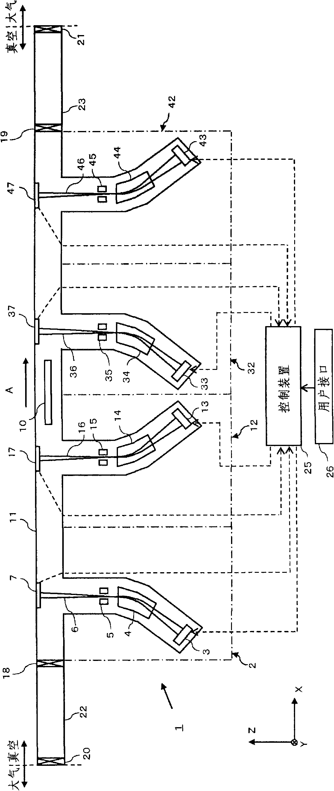
[0043] figure 1 It is a plan view showing an ion implantation apparatus 1 according to an embodiment of the present invention. figure 2 is viewed from the Z direction figure 1 Plan view of the interior of the processing chamber. Hereinafter, the overall structure of an ion implantation apparatus according to an embodiment of the present invention will be described with reference to these drawings.

[0044] In the present invention, the X direction is used as the transport direction of the substrate, the Y direction is used as the longitudinal direction of the ion beam, and the Z direction is used as the traveling direction of the ion beam irradiated on the glass substrate in the processing chamber, and these directions are mutually perpendicular. In addition, in the present invention, "ribbon-shaped ion beam" refers to an ion beam whose cross section is substantially rectangular when the ion beam is cut by a plane perpendicular to the traveling direction of the ion beam. ...


PUM


Abstract

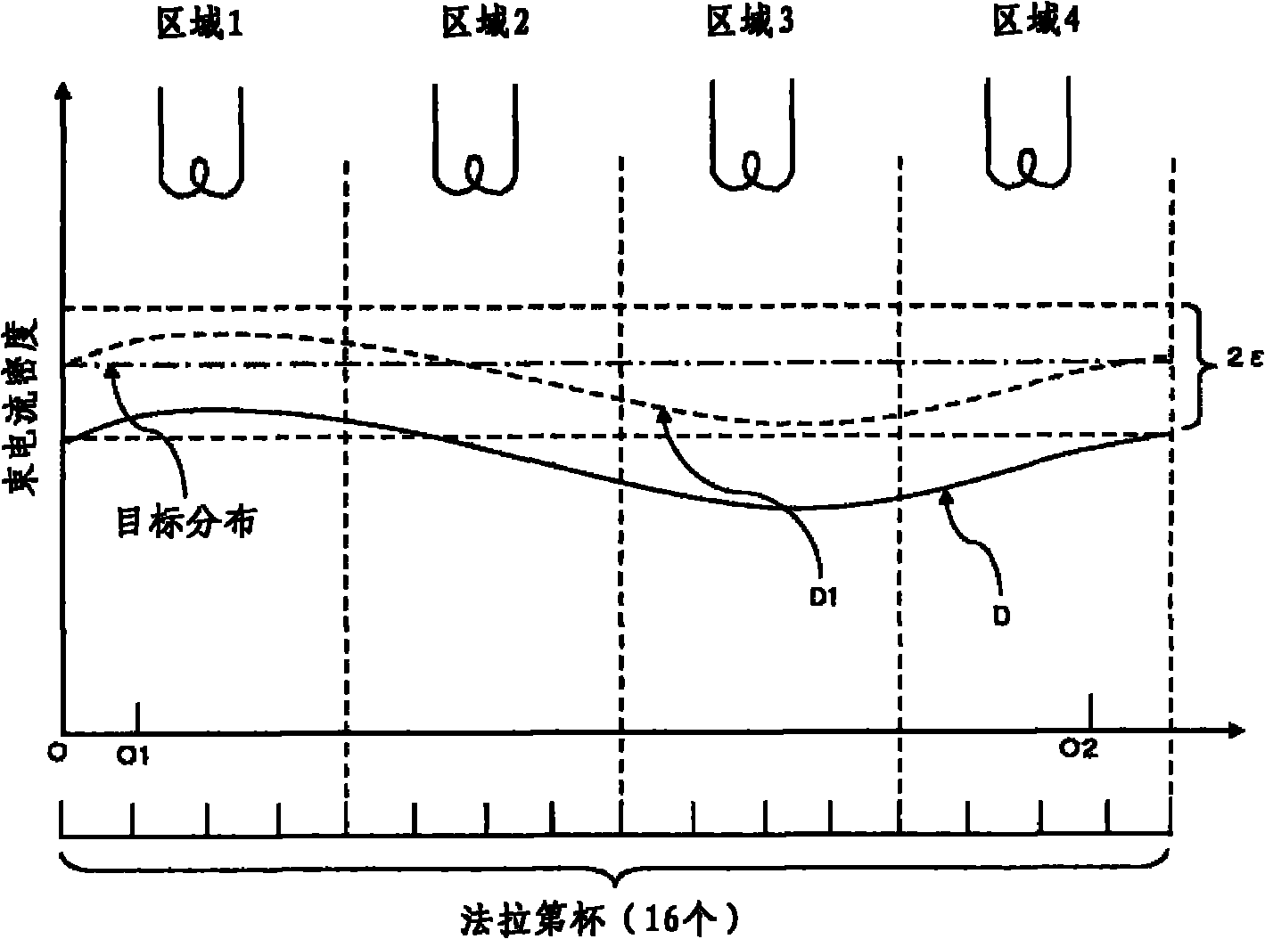
The invention provides an ion implantation device and an adjustment method of beam current density distribution. The irradiation areas of band-shaped ion beams in an amount of m (m is an integer over 2) at least partially overlap. In an ion implantation device which achieves regulated implantation amount distribution on a glass substrate, the beam current density distribution of each band-shaped ion beam can be adjusted with high efficiency. Each band-shaped ion beam is set as a target distribution of an adjustment target as a beam current density distribution. According to a pre-determined sequence, the beam current density distribution from a first band-shaped ion beam to a (m-1)th band-shaped ion beam, enabling the band-shaped ion beam to enter into a first allowing range with respect to the target distribution. Based on the difference between the distribution obtained from the adjustment result of each band-shaped ion beam and the distribution obtained from the target distribution of ion beams in an amount of m, new target distribution for adjusting a mth beam current density distribution is set, and the mth beam current density distribution is adjusted, enabling the mth beam current density distribution to enter into a second allowing range with respect to the new target distribution.

Description

technical field [0001] The present invention relates to an ion implanter for forming a predetermined implantation amount distribution on a glass substrate by overlapping areas irradiated with a plurality of ribbon ion beams, and a method for adjusting beam current density distribution used in the ion implanter. Background technique [0002] In recent years, the upsizing of liquid crystal products represented by liquid crystal televisions has been remarkable. In the semiconductor manufacturing process, in order to process more liquid crystal panels in one process, attempts have been made to increase the size of glass substrates and obtain multiple liquid crystal panels from large glass substrates. An ion implantation apparatus, which is one of semiconductor manufacturing apparatuses, is required to be compatible with such a large glass substrate. [0003] In order to meet such demands, the ion implantation apparatus described in Patent Document 1 has been developed so far. ...

Claims


Application Information

Patent Timeline
Patent Type & Authority Applications(China)
IPC IPC(8): H01J37/317H01J37/304
Inventor 中尾和浩
Owner 神商精密器材(扬州)有限公司
Learn More