Phase-locked circuit

A phase-locked loop and circuit technology, applied in the direction of electrical components, automatic power control, etc., can solve problems such as cost increase, and achieve the effects of improving stability, saving hardware space, and saving manufacturing costs

Active Publication Date: 2012-07-18
MEDIATEK INC
View PDF0 Cites 0 Cited by
  • Summary
  • Abstract
  • Description
  • Claims
  • Application Information

AI Technical Summary

Problems solved by technology

Therefore, it is necessary to increase the capacitance value of the integral charge pump path as much as possible. However, increasing the capacitance value to meet the above conditions usually leads to an increase in cost

Method used


Image

  • Phase-locked circuit
  • Phase-locked circuit
  • Phase-locked circuit

Examples


Embodiment Construction

[0014] Certain terms are used throughout the specification and following claims to refer to particular components. It should be understood by those skilled in the art that hardware manufacturers may refer to the same component by different terms. This description and the following claims do not use the difference in name as a way to distinguish components, but use the difference in function of components as a criterion for distinguishing. The "comprising" mentioned throughout the specification and subsequent claims is an open term, so it should be interpreted as "including but not limited to". The term "coupled" herein includes any direct and indirect means of electrical connection. Therefore, if it is described that a first device is coupled to a second device, it means that the first device can be directly electrically connected to the second device, or indirectly electrically connected to the second device through other devices or connection means. . The subsequent descr...


PUM


Abstract

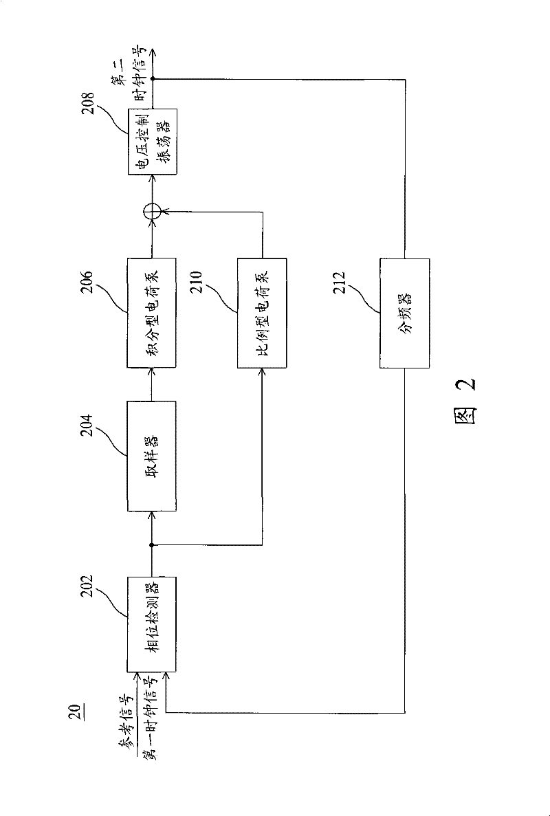
A phase-locked loop circuit. The phase-locked loop circuit comprises a phase detector, a proportional charge pump, a decimator, an integral charge pimp, and a voltage-controlled oscillator. The phase detector obtains an phase error information according to a phase difference between a reference signal and a clock signal input to the phase detector. The proportional charge pump coupled to the phase detector generates a first voltage according to the phase error information. The decimator generates a decimated version of the phase error information by a decimation factor of N. The integral charge pump generates a second voltage according to the decimated version of the phase error information. The voltage-controlled oscillator generating the clock signal according to a combination of the first and second voltages.

Description

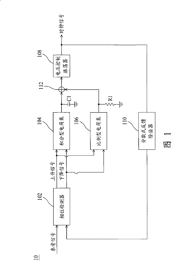
technical field [0001] The present invention mainly relates to a phase-locked loop (Phase-Locked Loop, PLL) circuit, in particular to a phase-locked loop circuit of a charge pump. Background technique [0002] A phase locked loop circuit is used to generate or synthesize a periodic output signal having the same frequency and phase (constant phase and frequency) relative to the input signal. Phase-locked loop circuits are widely used in many types of measurement, microprocessor and communication applications. Wherein, one type of phase-locked loop is a charge pump phase-locked loop circuit. [0003] figure 1 It shows a traditional charge pump PLL circuit 10, which includes a phase detector (phase detector) 102, an integral charge pump 104, a proportional charge pump 106 and a voltage controlled oscillator (Voltage Controlled Oscillator, VCO) 108. The phase detector 102 will refer to the phase θ of the signal IN The phase θ of the feedback clock (feedback clock) signal ou...

Claims


Application Information

Patent Timeline
Patent Type & Authority Patents(China)
IPC IPC(8): H03L7/091
CPCH03L7/093H03L7/087H03L7/0893
Inventor 汪炳颖
Owner MEDIATEK INC
Why Eureka
Try Eureka