Parameter estimation of a thermal model of a power line

A technology of model parameters and power lines, applied to electrical components, circuit devices, AC network circuits, etc., can solve problems such as difficult pure static model tuning, unexplained line temperature and time-related characteristics, and achieve the effect of increasing reliability

Inactive Publication Date: 2009-08-12
ABB RES LTD
View PDF2 Cites 10 Cited by
  • Summary
  • Abstract
  • Description
  • Claims
  • Application Information

AI Technical Summary

Problems solved by technology

The standard is based on a purely static model that does not account for the time-dependent behavior of line temperature and is difficult to tune due to the many input parameter data that must be assumed and the need for detailed meteorological data

Method used


Image

  • Parameter estimation of a thermal model of a power line
  • Parameter estimation of a thermal model of a power line
  • Parameter estimation of a thermal model of a power line

Examples


Embodiment Construction

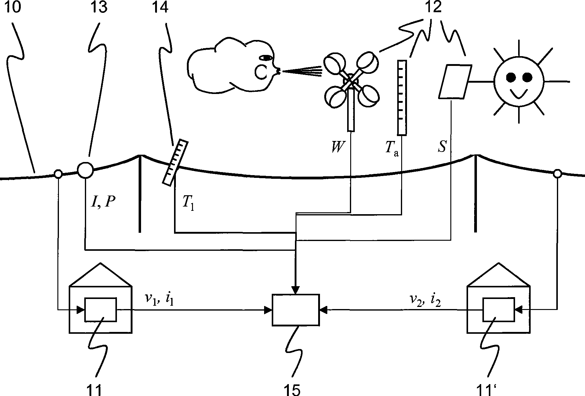
[0027] figure 1 Shown is a power line 10 which is part of a power system (not shown) comprising a plurality of generators and power consumers interconnected by a transmission grid. At both ends of the power line, two synchronized phasor measurement units (PMUs) 11, 11' are provided, and the synchronized vector measurement units are preferably installed in respective substation distribution rooms. Sensing devices for measuring weather quantities at one or more locations near power lines 10 are collectively referred to as weather stations 12 . A device 13 for measuring electrical quantities of a power line is schematically depicted, some of its components such as transformers or a process bus may also be used by the PMU. Also shown is a separate line temperature measuring device 14 . The weather station 12, the device 13 and the equipment 14 collect environmental conditions (wind speed W, wind direction, solar radiation S, ambient temperature T a , humidity), electrical quant...


PUM


Abstract

A relationship between a temperature T1 of a power line or power transmission conductor 10, an electrical quantity of the power line such as a current I or power flow P through the power line, as well as meteorological quantities or ambient conditions of the power line such as wind speed W, wind direction, humidity, solar radiation S and ambient temperatureTa, is established in the form of a thermal model of the power line. Values of the aforementioned quantities or variables are continuously measured, and the collected values of the quantities are evaluated in order to update model parameters of the thermal model during operation of the power line. In a preferred embodiment of the invention, an average temperature representative of the entire line is determined via two Phasor Measurement Units (PMU) 11, 11 ' providing synchronized phasor values from two ends of the power line. An ohmic resistance of the power line is computed from the phasor values, from which in turn the average line temperature can be derived.

Description

technical field [0001] The invention relates to the operation of power transmission lines. The invention proceeds from a method of estimating model parameters of a power line thermal model as described in the preamble of claim 1 . Background technique [0002] Due to the deregulation of the electricity industry and the liberalization of the electricity market, the amount of electricity exchanged between remote regions and the amount of commercial activity between different countries has steadily increased. Furthermore, due to emerging demands for asset optimization, the amount of power transmitted over existing networks has increased significantly, occasionally resulting in congestion, delivery bottlenecks and / or oscillations in parts of the transmission system. In particular, thermal constraints limit the power flow in critical power flow paths or power transmission channels that interconnect different regions. The main causes of thermal constraints are annealing of and / o...

Claims


Application Information

Patent Timeline
Patent Type & Authority Applications(China)
IPC IPC(8): H02J3/00H02H6/00
CPCH02H6/00H02H7/226
Inventor 马雷克·齐马彼得·科尔巴艾伯特·利尔布克特马茨·拉尔森
Owner ABB RES LTD
Why Eureka
Try Eureka