Beater disintegrating machine

A hammer mill and hammer technology, used in grain processing and other directions, can solve the problems of easy concave in the middle part of the sieve plate, hinder the powder from passing through the sieve holes, and affect the output of the pulverizer, so as to reduce the quality and ensure the Strength, the effect of improving stiffness

Active Publication Date: 2009-08-19
TSZJANSU CHZHEHNCHAN SIRIEHL OIL EHND FID MASHINERI KO
View PDF0 Cites 4 Cited by
  • Summary
  • Abstract
  • Description
  • Claims
  • Application Information

AI Technical Summary

Problems solved by technology

At present, the development of fish feed, shrimp feed and other aquatic products is relatively rapid, and the aperture of the sieve plate for the production of aquatic feed is relatively small, only φ1mm or even smaller, so the thickness of the sieve plate is very thin (generally the thickness is similar to the aperture). As a result, the middle part of the sieve plate is easy to be concave, and the middle part of the sieve plate is easily damaged by collision with the hammer on the rotor, etc. The part of the sieve plate is damaged, and the whole sieve plate must be replaced, which is a serious waste; During the crushing process, the material will run to both sides along the axial direction, resulting in uneven load on the hammer blades in the entire axial direction, and the hammer blades at both ends wear quickly and affect the output of the crusher.
When crushing, the material is driven by the hammer, and it is very easy to form a powder circulation layer on the surface of the sieve plate, which rotates circumferentially with the hammer, preventing the powder from passing through the sieve hole, and affecting the output of the pulverizer, especially in the When using a small-diameter sieve plate (below φ1.5mm), the output reduction is particularly obvious
Due to the irregular wear of the hammer or other parts, it will cause severe vibration during operation

Method used


Image

  • Beater disintegrating machine
  • Beater disintegrating machine
  • Beater disintegrating machine

Examples


Embodiment Construction

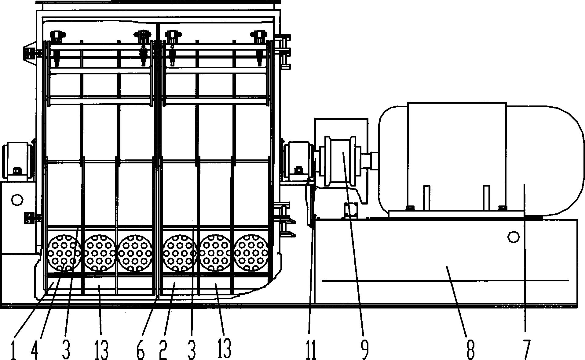
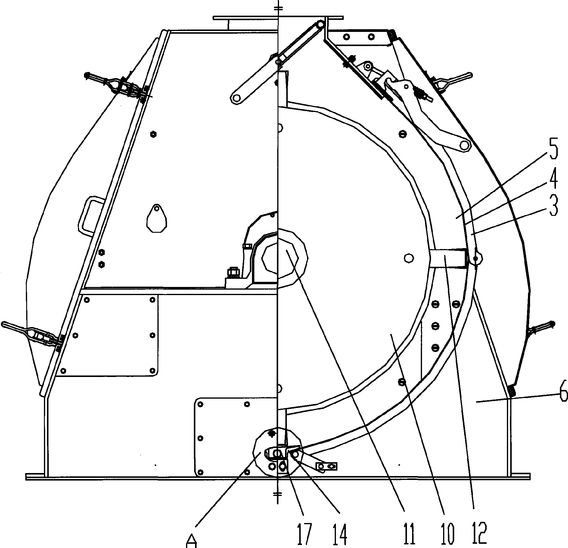
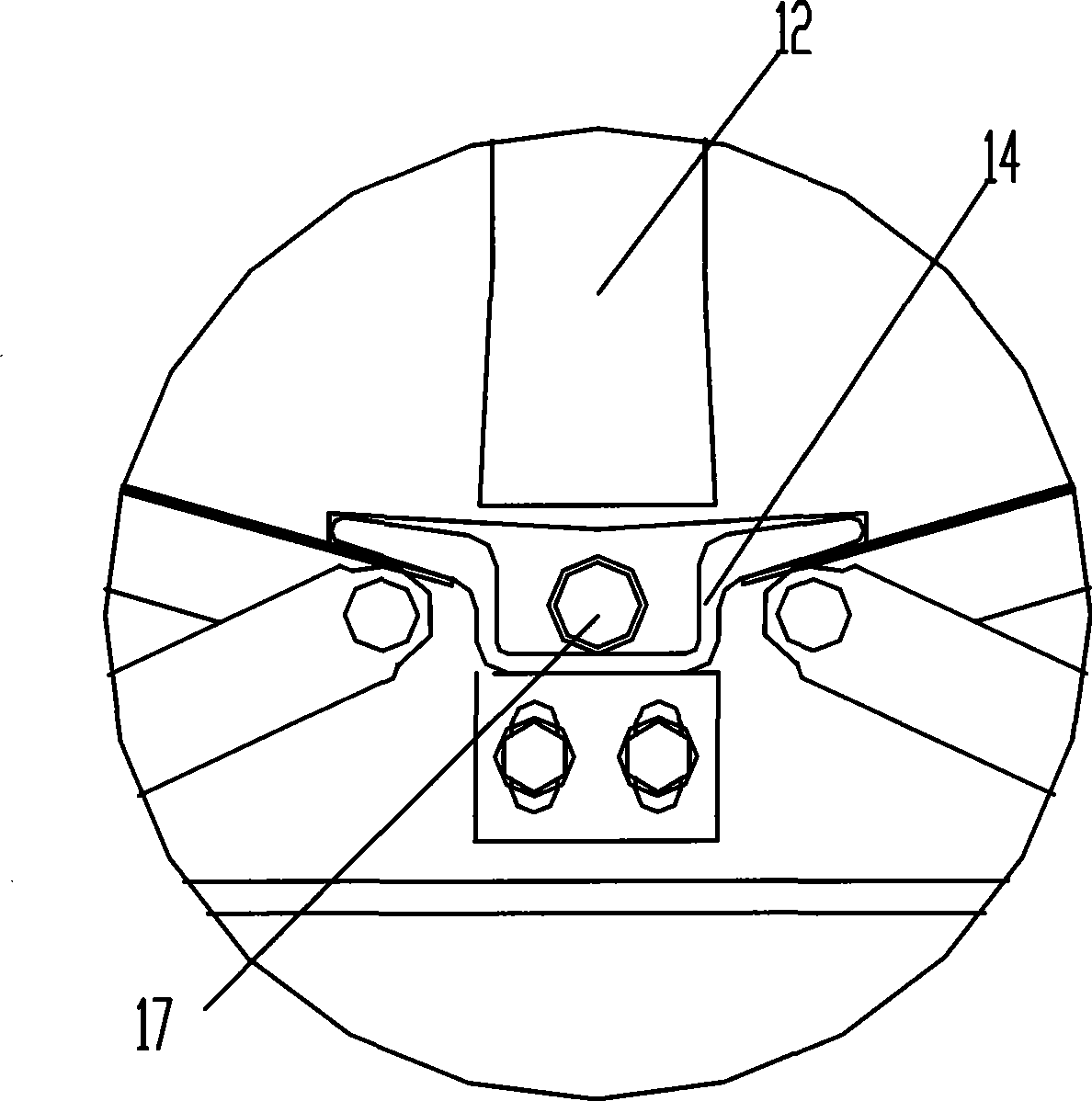
[0030] Such as Figure 1-2 In the embodiment 1 shown in , 7, the hammer mill mainly includes: a press screen frame 3, a sieve plate 4, a sieve plate frame 5, a motor 7, a frame 8, a coupling 9, a rotor 10, and a rotor shaft 11 , Hammer 12, secondary crushing chamber 14 and large spacer. The motor 7 installed on the machine base 8 is connected with the pulverizer rotor 10 through a shaft coupling 9 . The rotor 10, the sieve plate 4 and the sieve plate frame 5 jointly form a large crushing chamber, the secondary crushing chamber 14 is located at the lower end of the large crushing chamber, and the sieve plate 4 is tightly pressed on the sieve plate frame 5 by the pressing screen frame 3. The rotor shaft 11 of the rotor 10 is connected with the shaft coupling 9, and many hammer blades 12 are housed on the rotor 10. A large spacer is arranged between two adjacent hammer frame plates of the rotor shaft 11. The large spacer includes the inner edge of the spacer and the outer edge ...


PUM


Abstract

The invention discloses a hammer plate type crushing machine, and belongs to the field of a hammer plate type crushing machine. The crushing machine comprises a pressing screen rack, a screen plate, a screen plate rack, a motor, a machine base, a junction box, a rotor, a rotor shaft and hammer plates, wherein the motor arranged on the machine base is connected with the rotor of the crushing machine by the junction box; the rotor, the screen plate and the screen plate rack jointly form a crushing room; the rotor shaft of the rotor is connected with the junction box, and the rotor is provided with a plurality of hammer plates; a big separation sleeve is arranged between two adjacent hammer stand plates of the rotor shaft, the big separation sleeve comprises an inner edge of the separation sleeve and an outer edge of the separation sleeve, both sides of the inner and the outer edges of the separation sleeve are closely and fixedly connected with the adjacent hammer stand plates respectively; the inner edge of the separation sleeve is arranged on the rotor shaft, and the outer edge of the separation sleeve is arranged on the inner side of the mounting position of the hammer plates, and is 1 to 60mm away from the moving track of the hammer plates. Compared with prior art, the crushing machine has the advantages of improving the parts of the rotor-big separation sleeve, enhancing the operational balance of the rotor and lowering the influence on operational balance of the rotor due to wearing of parts.

Description

technical field [0001] The invention relates to a hammer mill, in particular to the improvement of the sieve plate, the rotor and the crushing chamber of the hammer mill. Background technique [0002] At present, the large spacer sleeve on the rotor spindle of the hammer mill is a solid circular sleeve, as attached Figure 10 As shown, this large spacer includes a circular spacer body 15-1 and a shaft hole 15-2, the shaft hole 15-2 is set in the center of the spacer body, the thickness of the spacer body is uniform, and the large spacer passes through the shaft hole 15-2. 2 The hammer frame plate installed on the main shaft of the pulverizer rotor to isolate the rotor. Due to the large difference between the outer diameter of the large spacer and the outer diameter of the hammer frame plate, the outer periphery of the hammer frame plate is prone to vibration during the high-speed operation of the rotor, thereby affecting the stability of the rotor operation. [0003] At the...

Claims


Application Information

Patent Timeline
Patent Type & Authority Applications(China)
IPC IPC(8): B02C13/04B02C13/26B02C13/288
Inventor 郝波贺志昌赵庚福姜伟忠周育东洑飞波
Owner TSZJANSU CHZHEHNCHAN SIRIEHL OIL EHND FID MASHINERI KO
Why Eureka
Try Eureka