Laser cutting nozzle

A laser cutting and cutting nozzle technology, which is applied in laser welding equipment, welding equipment, metal processing equipment, etc., can solve the problems of damaging the lens and reducing the service life of the lens

Inactive Publication Date: 2009-08-19
HANS LASER TECH IND GRP CO LTD
View PDF0 Cites 8 Cited by
  • Summary
  • Abstract
  • Description
  • Claims
  • Application Information

AI Technical Summary

Problems solved by technology

During the laser cutting process, the airflow is ejected upwards from the cutting head, and the molten or gasified material is blown out from the bottom of the incision, and the molten or gasified material becomes oxide slag, which is generally blown out

Method used


Image

  • Laser cutting nozzle
  • Laser cutting nozzle
  • Laser cutting nozzle

Examples


Embodiment Construction

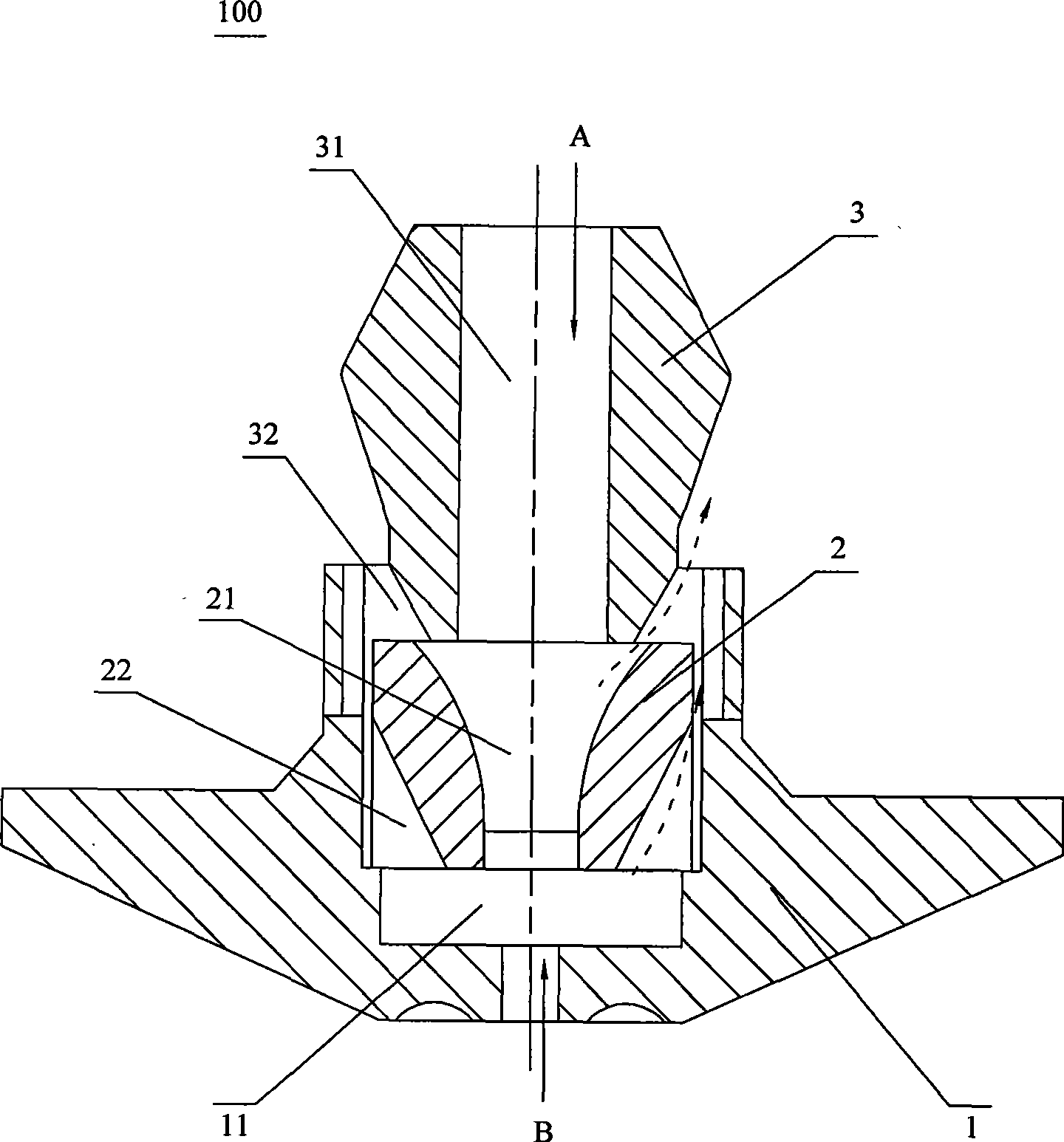
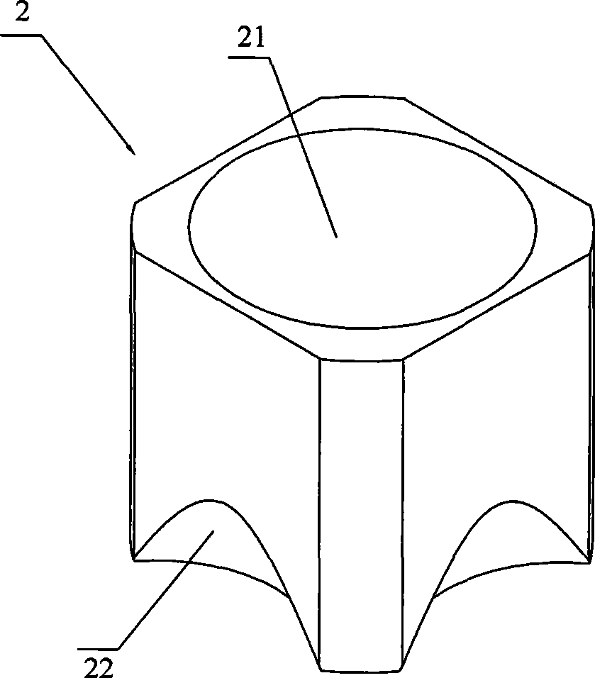
[0023] see figure 1 , is a structural schematic diagram of the laser cutting nozzle of the present invention. In order to reduce and prevent the oxidized slag (not shown) generated during laser cutting from damaging the lens, thereby reducing the service life of the lens, the laser cutting nozzle 100 mainly It includes a cutting nozzle main body 1, a concentrator 2 fixed in the cutting nozzle main body 1 and a slag return device 3, wherein the slag return device 3 is adjacent to the flow concentrator 2, in fact, the slag return device 3 , concentrator 2 and cutting nozzle main body 1 are arranged in sequence.

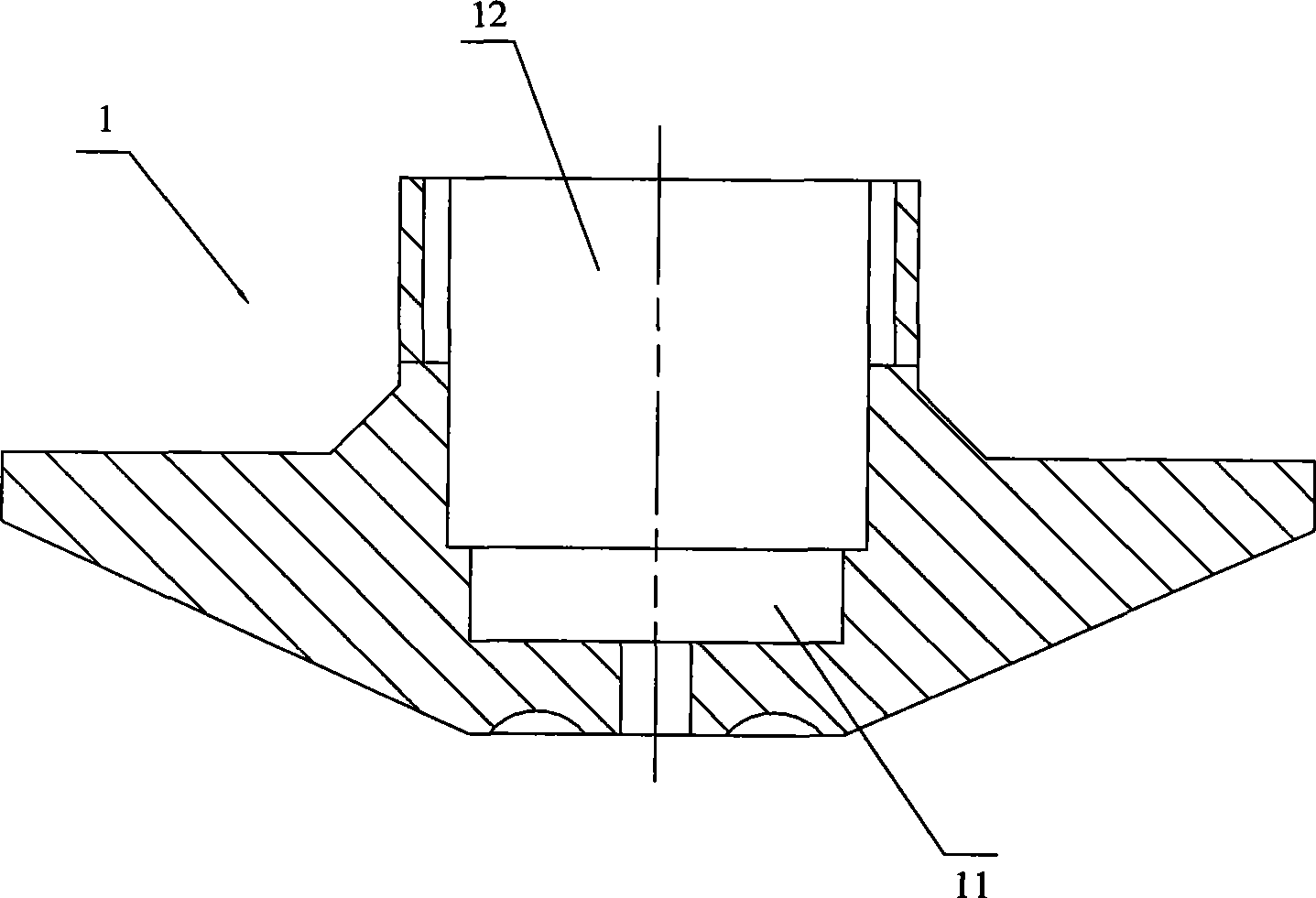
[0024] Among them, such as figure 1 and figure 2 , the cutting nozzle main body 1 is used to cut the workpiece, including: a first storage cavity 11 and a storage space 12 connected with the first storage cavity 11, wherein the concentrator 2 and the slag returner 3 are adjacent to each other and are fixed in the storage space. In space 12.

[0025] Among them, suc...


PUM


Abstract

The invention provides a laser cutting nozzle, which consists of a cutting nozzle main body, a fluid collector and a slag returner, wherein the laser cutting nozzle has a first accommodating chamber, a second accommodating chamber and a third accommodating chamber; the bottom of the slag returner is provided with a plurality of slag returning ports adjacent to the second accommodating chamber; and when gases flow, fluid in different accommodating chambers has different flow rates to generate different pressures so as to generate pressure difference, and all motion vectors are consistent. When the cutting nozzle works, generated oxidizing slag is splashed into the chambers, the different pressure differences in the chambers force the oxidizing slag to change motion direction to move toward the direction of the slag returning ports; the slag returner is arranged in a chamber to limit the motion space of the oxidizing slag and resist the motor ability of the oxidizing slag; and the vectors of the gases consistently move towards the nozzle, so the oxidizing slag is cut down or stopped and cannot move to the section of a lens so as to achieve the aims of reducing and stopping lens damage.

Description

【Technical field】 [0001] The invention relates to a laser cutting nozzle which prevents slag spraying from damaging the lens. 【Background technique】 [0002] The laser cutting machine uses high-energy laser beams to irradiate the surface of the workpiece, so that the irradiated area is partially melted and vaporized, so as to achieve the purpose of cutting the workpiece. Because the laser is focused by a special optical system and becomes a very small spot, the energy density is high. Therefore, it has a better effect on cutting some materials with relatively high hardness, such as cemented carbide, ceramics, and diamond. During the laser cutting process, the airflow is ejected upwards from the cutting head, and the molten or gasified material is blown out from the bottom of the incision, and the molten or gasified material becomes oxide slag, which is generally blown out from the bottom upwards, and is directly punched on the Although the oxidized slag on the lens of the l...

Claims


Application Information

Patent Timeline
IPC IPC(8): B23K26/42B23K26/14B23K26/142B23K26/70
Inventor 高云峰詹建国
Owner HANS LASER TECH IND GRP CO LTD
Why Eureka
Try Eureka