A front suspension assembly

A front mount and assembly technology, which is applied to power plants, jet propulsion devices, internal combustion propulsion devices, etc., can solve the problems of increasing the stiffness of the front mount, worsening comfort, and difficult layout, avoiding vibration and noise. Increase, improve service life, and ensure the effect of comfort

Active Publication Date: 2022-05-03
ANHUI JIANGHUAI AUTOMOBILE GRP CORP LTD
View PDF6 Cites 0 Cited by
  • Summary
  • Abstract
  • Description
  • Claims
  • Application Information

AI Technical Summary

Problems solved by technology

[0006] 1. The front suspension assembly is in the W positive unlimited position structure. When the powertrain jumps up, in order to limit the movement of the powertrain within the required space, it is necessary to increase the stiffness of the front suspension, resulting in increased vibration and noise in the car. large, poor comfort
[0007] 2. The positive direction of the front suspension assembly W is the stretching direction of the rubber and has an infinite structure. The durability of the rubber in the stretching direction is poor, which causes the rubber to age and break easily, and the consistency of the vulcanization process is also likely to cause the main body of the rubber to break. Fracture or disengagement of the vulcanized layer, if the above situation occurs, the front suspension assembly cannot support and limit the power assembly, resulting in the failure of the suspension system structure and causing safety accidents
[0008] 3. Since the cushion cover is assembled on the outside of the suspension cushion as a limit device and moves with the engine, it must be ensured that it does not interfere with other components on the movement path, which takes up a lot of space, resulting in insufficient space for other components , it is more difficult to arrange

Method used


Image

  • A front suspension assembly
  • A front suspension assembly
  • A front suspension assembly

Examples


Embodiment Construction

[0043] In order to enable those skilled in the art to better understand the technical solution of the present invention, the solution will be further described in detail below in conjunction with specific embodiments.

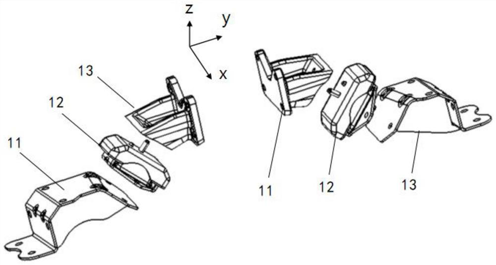
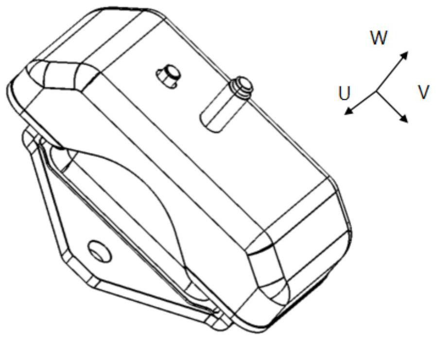
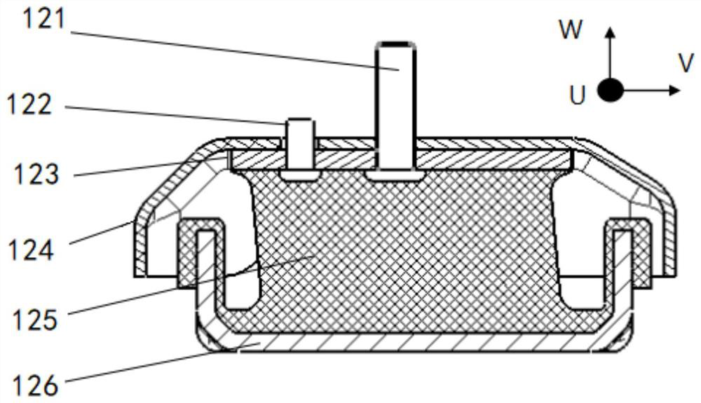
[0044] like Figure 5 to Figure 10 As shown, the embodiment of the present invention provides a front suspension assembly, which includes a front suspension upper plate 21, a mounting stud 23, a positioning pin 22, a front suspension lower plate 24, a rubber main spring 31, a limit screw column 41, the front suspension upper plate 21 is arranged on the top surface of the rubber main spring 31, and the front suspension lower plate 24 is arranged on the bottom surface of the rubber main spring 31; the positioning pin 22 and The mounting studs 23 are respectively arranged on the front suspension upper plate 21, and the rubber main spring 31 is provided with a first accommodation hole 311 for accommodating the limit head of the positioning pin, for accommodating th...


PUM


Abstract

The invention provides a front suspension assembly, which includes a front suspension upper plate, mounting studs, positioning pins, a front suspension lower plate, a rubber main spring, and a limit stud. On the top surface of the rubber main spring, the front suspension lower plate is arranged on the bottom surface of the rubber main spring; the positioning pin and the mounting stud are respectively arranged on the front suspension upper plate, and the rubber The main spring is provided with a first accommodating hole for accommodating the limit head of the positioning pin and a second accommodating hole for accommodating the limit head of the mounting stud; The lower plate of the front suspension and the rubber main spring are connected to the limit head of the installation stud, the limit stud is coaxial with the installation stud, and the limit head of the limit stud is located at the front suspension below the lower plate. The invention enables the rubber main spring to be well limited in all directions, improves the service life of the rubber main spring, saves space and ensures the comfort of the vehicle.

Description

technical field [0001] The invention belongs to the technical field of automobile suspension systems, and in particular relates to a front suspension assembly. Background technique [0002] In modern powertrain longitudinally mounted models, the mount system is required to have the functions of vibration isolation and control of powertrain displacement. Generally, a three-point mount arrangement with two front and one rear or a four-point mount arrangement with two front and two rear is adopted. The suspension installed on the engine side is called the front suspension assembly, and generally adopts a V-shaped left-right symmetrical layout structure with a certain inclination angle, such as figure 1 As shown, the front and rear mounts should have limit structures in all directions to ensure uniform stress on each mount and effectively limit the displacement of the powertrain. Wherein, the vehicle body side mounting bracket 13 is stationary relative to the vehicle body; the ...

Claims


Application Information

Patent Timeline
Patent Type & Authority Patents(China)
IPC IPC(8): B60K5/12
CPCB60K5/1208
Inventor 刘双双陈韬李二涛薛博之
Owner ANHUI JIANGHUAI AUTOMOBILE GRP CORP LTD
Why Eureka
Try Eureka