Micro laser beam precise finishing optical device

A technology of precision machining and optical devices, applied in optics, optical components, laser welding equipment, etc., can solve the problems of no visible light coaxial positioning indication, difficulty in system assembly and adjustment, inability to achieve random detection, etc., to achieve flatness adaptability The effect of strong, long processing distance and convenient system adjustment

Inactive Publication Date: 2009-08-19
XIAMEN UNIV
View PDF1 Cites 19 Cited by
  • Summary
  • Abstract
  • Description
  • Claims
  • Application Information

AI Technical Summary

Problems solved by technology

This technology can solve the problems of small effective processing thickness of the workpiece in traditional laser processing, and the taper and roughness of the processing surface. The guiding laser s

Method used


Image

  • Micro laser beam precise finishing optical device
  • Micro laser beam precise finishing optical device
  • Micro laser beam precise finishing optical device

Examples


Embodiment Construction

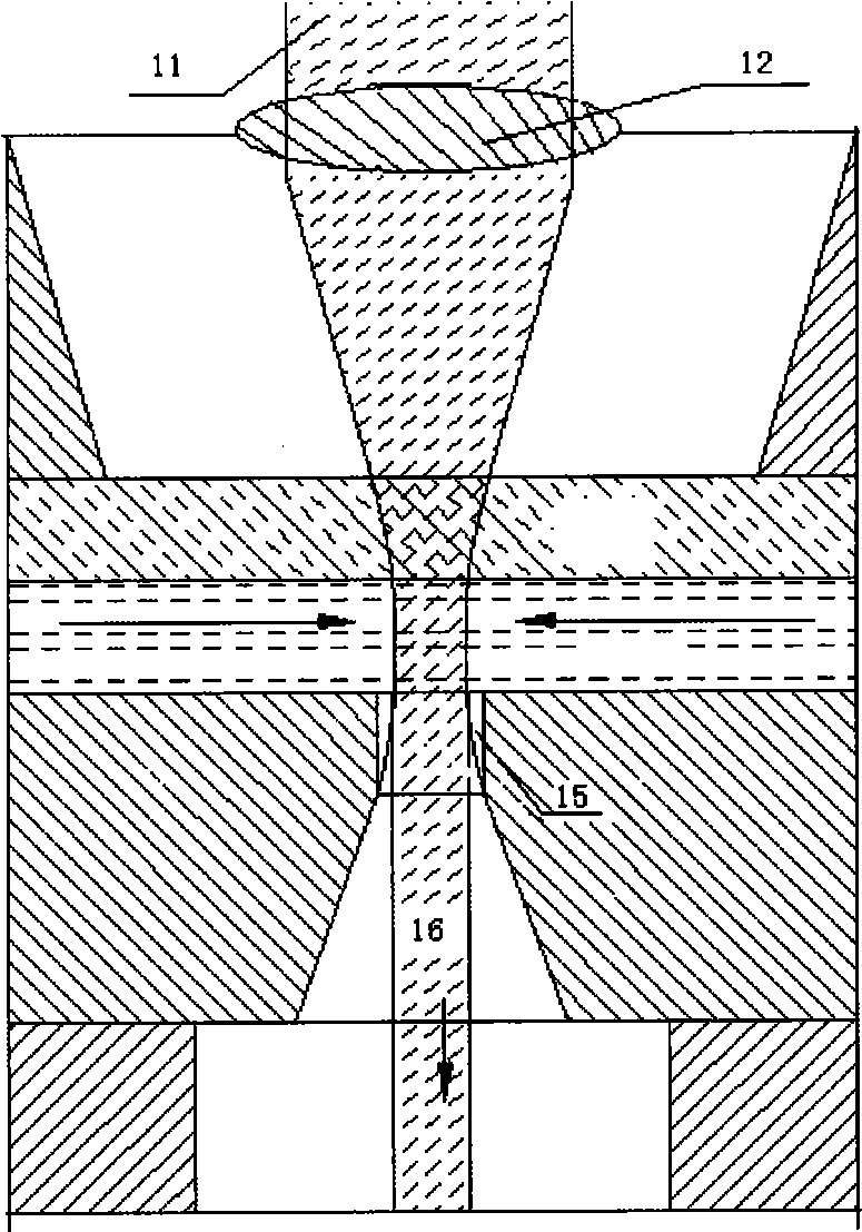
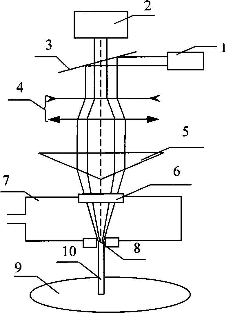
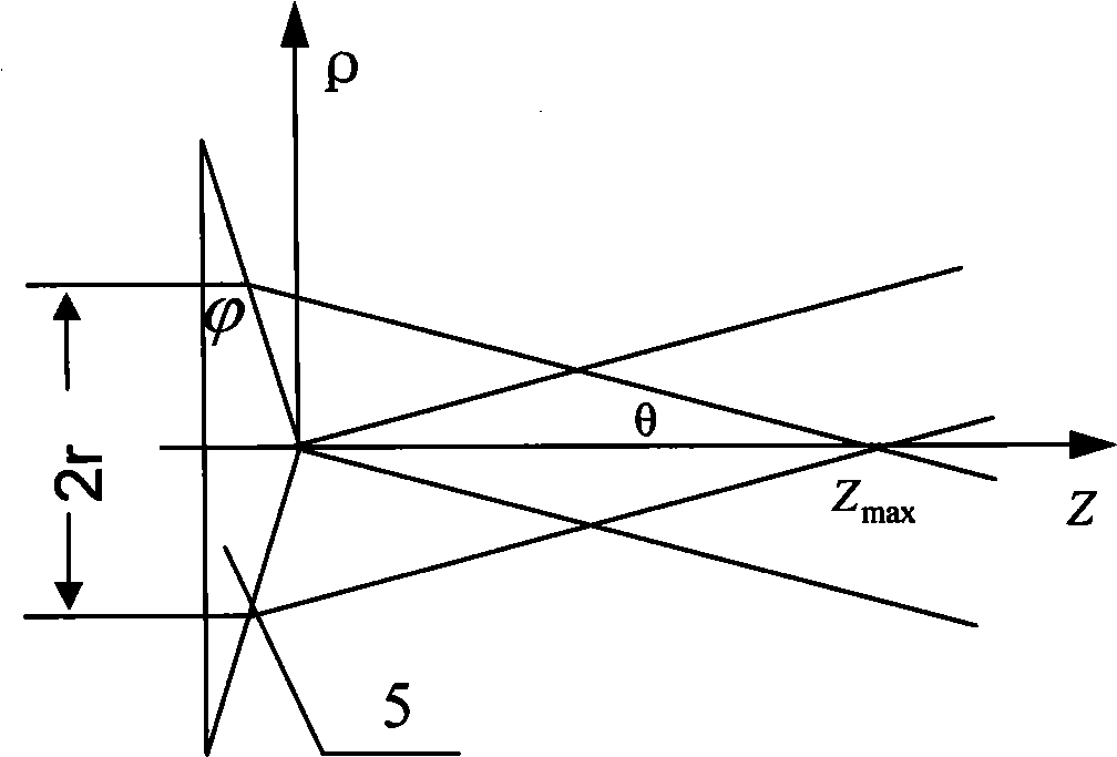
[0015] see figure 2 and 3 , The present invention is equipped with a laser 1, a visible light source 2, a plane mirror 3, a beam expander collimator 4, an axicon 5, an optical window 6, a pressure fluid chamber 7 and a nozzle microhole 8.

[0016] The plane mirror 3 is located in front of the laser 1 and the visible light source 2, the laser beam emitted by the laser 1 is coupled with the light beam of the visible light source 2 through the plane mirror 3, the beam expander collimator 4 is located in front of the plane mirror 3, and the axicon 5 is located in front of the beam expander collimator 4, The pressure fluid chamber 7 is located in front of the axicon 5, the optical window 6 is located at the top of the pressure fluid chamber 7, the nozzle microhole 8 is located at the bottom of the pressure fluid chamber 7, and the beam coupled by the plane mirror 3 is coupled with the beam expander collimator 4 and the axicon 5. The optical window 6 and the nozzle microhole 8 are...


PUM


Abstract

The invention discloses a micro-laser beam precision machining optical device, and relates to a precision machining device. The invention provides the micro-laser beam precision machining optical device for laser precision machining, which is provided with visible light coaxial positioning indication and can conveniently realize direct coupling of diffraction-free beams and nozzle micropores. The micro-laser beam precision machining optical device is provided with a laser, a visible light source, a flat mirror, a beam expanding collimator, an axicon, an optical window, a pressure fluid chamber and nozzle micropores, wherein the flat mirror is positioned in front of the laser and the visible light source; laser beams emitted by the laser are coupled with beams of the visible light source through the flat mirror; the beam expanding collimator is positioned in front of the flat mirror; the axicon is positioned in front of the beam expanding collimator; the pressure fluid chamber is positioned in front of the axicon; the optical window is arranged on the top of the pressure fluid chamber; the bottom of the pressure fluid chamber is provided with the nozzle micropores; and the beams coupled through the flat mirror are coaxial with the beam expanding collimator, the axicon, the optical window and the nozzle micropores.

Description

technical field [0001] The invention relates to a precision processing device, in particular to a micro-laser beam precision processing optical device using water-guided laser technology. Background technique [0002] Richerzhagen Bernold of the Swiss Federal University of Technology studied the phenomenon of light transmission in water beams, and developed it into a microfabrication technology, which became an international patent technology (WO 95 / 32834). figure 1 As shown, the low pressure is used to generate the fine water jet beam 16, and the laser beam 11 is focused on the outlet of the nozzle microhole 15 with the traditional positive lens 12, and the laser beam is guided by the total reflection of the laser beam on the contact surface of water and air. The beam acts on the workpiece to be processed, and its effect is similar to the traditional glass optical fiber method. This technology can solve the problems of small effective processing thickness of the workpiece ...

Claims


Application Information

Patent Timeline
IPC IPC(8): B23K26/42G02B17/08G02B27/09B23K26/064
Inventor 黄元庆叶瑞芳沈阳
Owner XIAMEN UNIV
Why Eureka
Try Eureka