

Variable valve system
A valve, variable technology, applied in the direction of non-mechanical actuated valves, output power, mechanical equipment, etc., can solve the problems of reduced valve overlap angle, unfavorable intake air, constant intake continuous angle, etc.
Inactive Publication Date: 2009-08-19
蔡学功
View PDF0 Cites 4 Cited by
- Summary
- Abstract
- Description
- Claims
- Application Information
AI Technical Summary
Problems solved by technology
[0002] In order to generate greater power, modern internal combustion engines have higher and higher speeds and wider speed ranges; in order to achieve better ventilation, this requires variable valve timing to meet the needs of various working conditions; for this reason Many internal combustion engines use a variable valve timing mechanism, generally a variable valve mechanism with a variable cam phase; however, the intake continuous angle of this variable valve mechanism remains unchanged. Although the intake delay closing angle may be increased at high speed, the valve The fold angle is reduced; it is not conducive to air intake at high speed
Method used
View moreImage
Smart ImageViewing Examples

Examples
Embodiment Construction
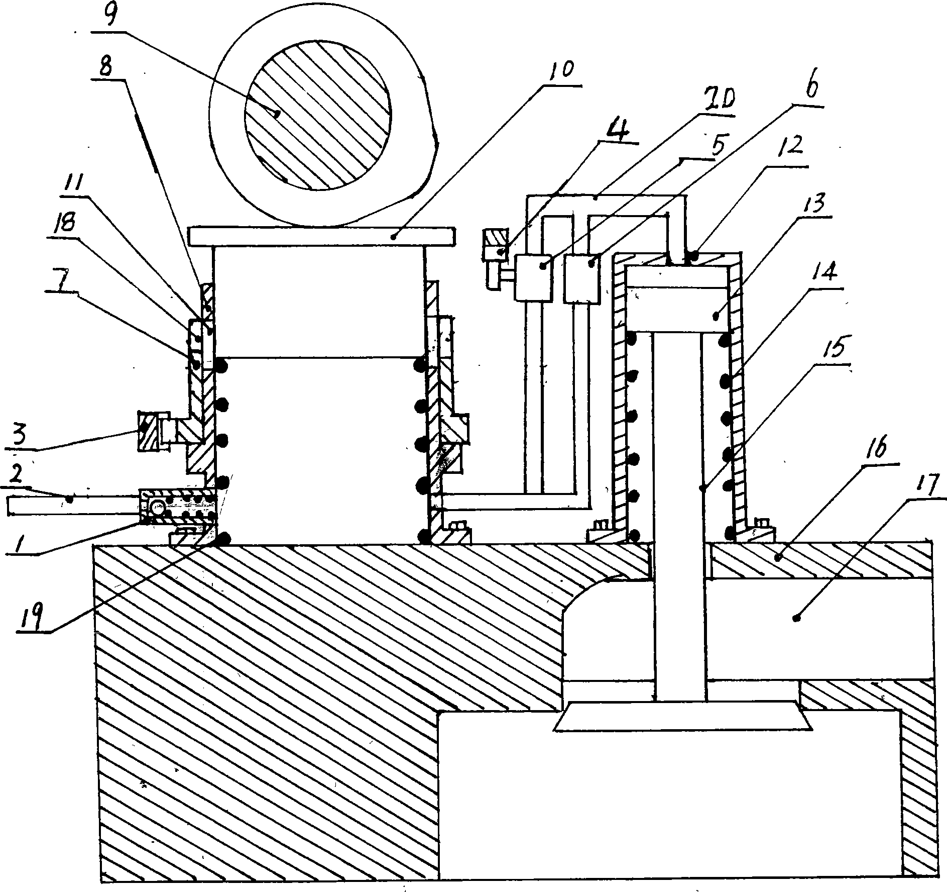
[0008] In the accompanying drawings, the valve piston is placed in the valve piston cylinder and fixed together with the valve tail; the valve piston cylinder and the main piston cylinder are fixed on the cylinder head with screws; the main piston is placed on the upper part of the main piston cylinder, and the upper end is connected with the cam The shaft contacts, and the main piston spring is installed at the lower end of the main piston.
Login to View More PUM
 Abstract
The invention provides a changeable valve system, wherein the switch of the internal-combustion engine valve can be controlled by hydraulic pressure and the phase of valve distribution can be changed continuously. The system consists of a cylinder cap, a valve, a valve piston, a valve piston cylinder, a main piston, a main piston cylinder and a cam shaft. The working principle is as follows: when the internal-combustion is working, the cam pushes the main piston downwards, when the lower end of the main piston moves downwards to the upper brim of the slant face of a regulator cylinder before sealing the oil outlet, the valve piston stands still, and the valve is in a closed state under the action of the valve spring; when the lower end of the main piston moves downwards to the upper brim of the slant face of a regulator cylinder and seals the oil outlet, the oil in the main piston cylinder enters into the valve piston cylinder by passing an oil transporting pipe to push the valve piston to open the valve, so that the gas enters into or is discharged out of a combustion chamber through a gas channel, thus realizing gas exchange. The opening time and the lift range of the valve can be regulated by just adjusting the position of the regulator cylinder, the delay shut angle of the valve can be changed by regulating the opening degree of a throttle valve, and the phase of the valve distribution can be changed continuously.
Description
technical field [0001] The invention belongs to the technical field of internal combustion engines. Background technique [0002] In order to generate greater power, modern internal combustion engines have higher and higher speeds and wider speed ranges; in order to achieve better ventilation, this requires variable valve timing to meet the needs of various working conditions; for this reason Many internal combustion engines use a variable valve timing mechanism, generally a variable valve mechanism with variable cam phase; however, the intake continuous angle of this variable valve mechanism remains unchanged. Although the intake delay closing angle may be increased at high speed, the valve The fold angle is reduced; it is not conducive to air intake at high speed. Contents of the invention [0003] The object of the present invention is to provide a variable valve system that uses hydraulic pressure to control the intake and exhaust of the internal combustion engine, wh...
Claims
Login to View More Application Information
Patent Timeline
 IPC IPC(8): F01L13/00F01L1/34F01L9/02F02D13/02F01L9/11
CPCY02T10/18Y02T10/12
Inventor蔡学功
Owner蔡学功