B-axis cutter holder device of a turn-milling complex machining center

A composite machining center and composite processing technology, which is applied in positioning devices, metal processing, metal processing equipment, etc., can solve the problems of difficult to meet the processing accuracy requirements of parts, damaged spindle bearing accuracy, and high rigidity requirements of the mechanism, so as to improve rigidity, cutting tools, etc. The effect of short overhangs and refined angular positioning

Inactive Publication Date: 2009-08-26
SHENYANG NO MACHINE TOOL FACTORY
View PDF0 Cites 12 Cited by
  • Summary
  • Abstract
  • Description
  • Claims
  • Application Information

AI Technical Summary

Problems solved by technology

In recent years, the B-axis tool holder device of the domestic and foreign turning-milling compound machining center has only one tool installation position, and all the tools are installed on the power spindle. It needs to be rotated, and the working state is different from that of the rotary tool. Therefore, it is necessary to set a set of gear plate locking structure at the front end of the output shaft of the power spindle, which increases the distance between the spindle bearing support and the tip of the rotary tool. When the length of the installed tool bar is more than 400mm When boring and milling tools, the overhang is too long, and it is difficult to meet the machining accuracy requirements of the parts only by connecting the short taper tool holder with the power spindle; The main shaft bearing is stressed, and the rough machining of large-scale rotary parts requires large blank allowance, large vibrat

Method used


Image

  • B-axis cutter holder device of a turn-milling complex machining center
  • B-axis cutter holder device of a turn-milling complex machining center
  • B-axis cutter holder device of a turn-milling complex machining center

Examples


Embodiment Construction

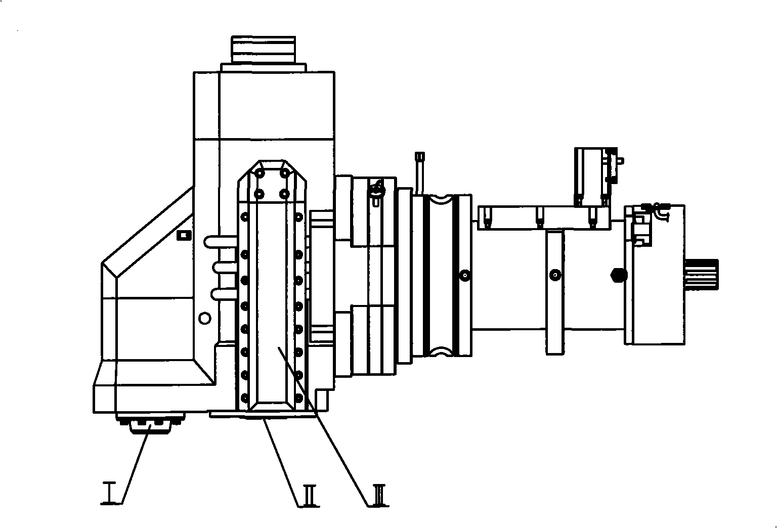
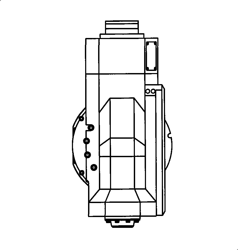
[0016] The B-axis tool holder device of the turning-milling compound machining center is installed on the B-axis of the five-axis turning-milling compound processing machine tool, and has supporting electrical, hydraulic, cooling, and pneumatic control parts that are combined with the system on the machine tool. The B-axis motor passes through The worm gear drives the incoming shaft, such as figure 1 and figure 2 As shown, it is characterized in that the turning tool, the tool for special needs and the rotating tool whose overhang length meets the requirements of the tool are separated, and are respectively set at the three-point position of the B-axis tool holder: the indexable turning tool is installed at the left end I of the B-axis tool holder device No. position; the rotary tool whose overhang length meets the requirements of the tool is set at No. II position directly in front of the B-axis tool post, which can be used for boring, milling, drilling, tapping and other pr...


PUM


Abstract

A B-axis cutter holder device of a turn-milling complex machining center is disclosed, which is mounted on a B-axis of a five-axis turn-milling complex machine and is fitted with matched electric, hydraulic, cooling and pneumatic control parts that are correspondingly integrated with a system on the machine, and a B-axis motor drives a transmission axis via a worm gear; the device is characterized in that, a turning cutter, a rotating cutter, a boring cutter and a milling cutter for machining special parts are respectively arranged at three-point location of the B-axis cutter holder; the indexable turning cutter is mounted at location I at the left end of the B-axis cutter holder device; the rotating cutter of which an overhanging length accords with the use requirement of the cutter is arranged at location II right in front of the B-axis cutter holder and machining operations such as boring, milling, drilling, threading and the like can be implemented; the locations I and II are provided with standard cutter interfaces; an overhanging ultra-long cutter in a dovetail structure is arranged at location III at the side face of a B-axis box body, and standard cutter or a designated knife holder can be mounted by the replacement of connectors; the B-axis cutter holder device realizes dividing locking via three fluted disc structures of an immovable fluted disc, a movable fluted disc and a locking fluted disc. The separation of the cutter locations achieves the machining requirement of the B-axis at random location within a range of operating angles, thus solving three key technical problems of how to ensure the precision of a spindle of the rotating cutter, how to enhance the rigidness of a turning mechanism and how to remain the machining precision under a specific machining status.

Description

technical field [0001] The present invention relates to mechanical manufacturing equipment. Background technique [0002] The turning and milling compound machining center has the functions of turning, milling, drilling, boring, tapping, deep hole processing, turning and milling internal and external threads, etc. These functions are mainly realized by the B-axis tool holder device. Therefore, it is required that such devices can be installed with turning tools and various types of rotary tools. In recent years, the B-axis tool holder device of the domestic and foreign turning-milling compound machining center has only one tool installation position, and all the tools are installed on the power spindle. It needs to be rotated, and the working state is different from that of the rotary tool. Therefore, it is necessary to set a set of gear plate locking structure at the front end of the output shaft of the power spindle, which increases the distance between the spindle bearin...

Claims


Application Information

Patent Timeline
IPC IPC(8): B23Q3/00B23Q37/00
Inventor 李宪凯郭秀英李宏宇金明刚白紫山肖凯李剑
Owner SHENYANG NO MACHINE TOOL FACTORY
Why Eureka
Try Eureka