High-luminance LED illuminating energy-saving lamp with round luminous spots and electric torch

A high-brightness, energy-saving lamp technology, applied in lighting devices, lighting and heating equipment, portable lighting devices, etc., can solve the problems that cannot be used to make screw lamps, bayonet lamps, cannot produce, and uneven illumination , to achieve the effect of improving light efficiency and output power, long life, and uniform illumination

Inactive Publication Date: 2009-08-26
杭州顺博科技有限公司
View PDF1 Cites 2 Cited by
  • Summary
  • Abstract
  • Description
  • Claims
  • Application Information

AI Technical Summary

Problems solved by technology

Its shortcomings: First, it cannot be used to make screw lights, bayonet lights, downlights and other lightin

Method used


Image

  • High-luminance LED illuminating energy-saving lamp with round luminous spots and electric torch
  • High-luminance LED illuminating energy-saving lamp with round luminous spots and electric torch
  • High-luminance LED illuminating energy-saving lamp with round luminous spots and electric torch

Examples


Example Embodiment

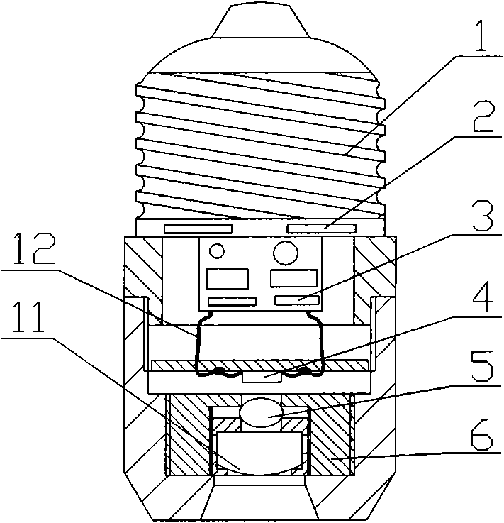
[0015] Example 1: Refer to the attached figure 1 . The high-brightness LED circular spot illuminates the energy-saving lamp. The power converter 3 converts AC power into DC low voltage and is located in the housing 9 (9 generally refers to the housing). The housing has a heat dissipation window 2, and the power converter 3 The input end is a screw cap 1 or a bayonet cap. The output end of the power converter 3 is connected to the LED chip 4 through a wire 12, and the LED chip 4 is located in the housing 9. The condenser lens 5 is a convex lens, the round spot shaping lens 11 is flat on one side, and the other side is a convex lens. The condenser lens 5 is located under the LED chip 4 through the frame 6 and the round spot shaping lens 11 is located on the condenser through the frame 6 Below the lens 5. The main optical axis of the condenser lens 5 and the circular spot shaping lens 11 are located on the same axis, and the illumination window at the lower end of the housing 9 is i...

Example Embodiment

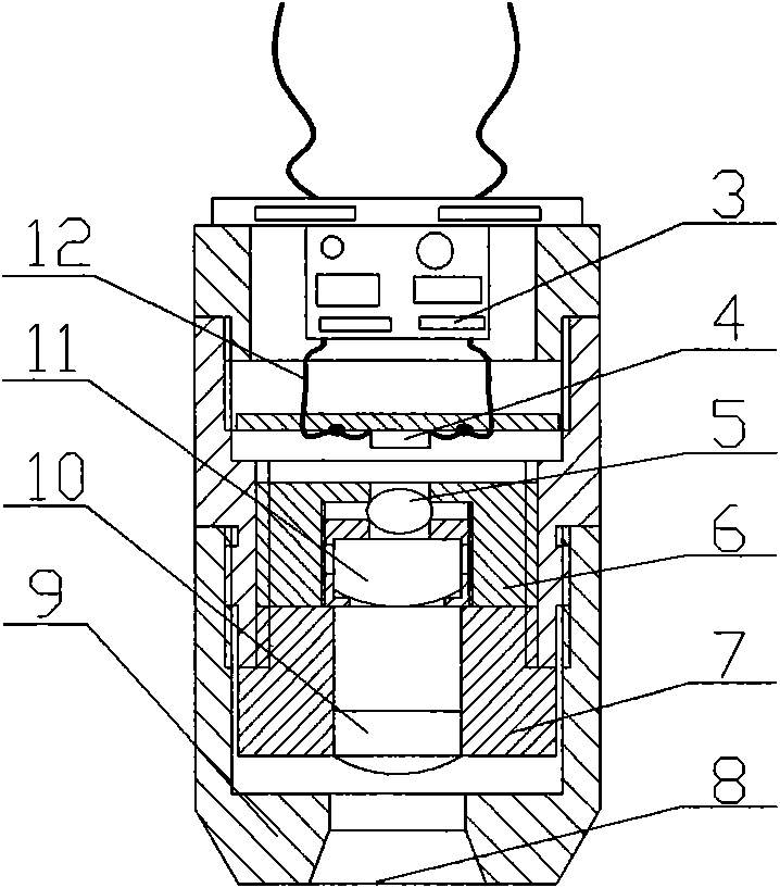
[0016] Embodiment 2: On the basis of Embodiment 1, the focal length between the condenser lens 5 and the circular spot shaping lens 11 is adjustable.

Example Embodiment

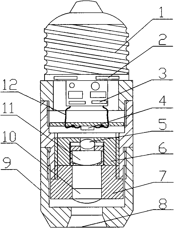
[0017] Example 3: Refer to the attached figure 2 . Example 1: Refer to the attached figure 1 . The high-brightness LED circular spot illuminates the energy-saving lamp. The power converter 3 converts AC power into DC low voltage and is located in the housing 9 (9 generally refers to the housing). The housing has a heat dissipation window 2, and the power converter 3 The input end is a screw cap 1 or a bayonet cap. The output end of the power converter 3 is connected to the LED chip 4 through a wire 12, and the LED chip 4 is located in the housing 9. The condenser lens 5 is a convex lens, the round spot shaping lens 11 is flat on one side, and the other side is a convex lens. The condenser lens 5 is located under the LED chip 4 through the frame 6 and the round spot shaping lens 11 is located on the condenser through the frame 6 Below the lens 5. The secondary spot shaping lens 10 is located under the circular spot shaping lens 11 through the frame 7. The main optical axis of the...


PUM


Abstract

The invention relates to a high-luminance LED illuminating energy-saving lamp with round illuminating luminous spots, wherein the input end of a power supply converter is connected with a power supply, the output end of the power supply converter is connected with an LED chip which is positioned in a shell, a collecting lens is positioned below the LED chip, and a round luminous spot forming lens is positioned below the collecting lens. The high-luminance LED illuminating energy-saving lamp has the following advantages: firstly, the light generated by a high-luminance LED chip forms the round luminous spots with even and ordered illumination; secondly, because the LED chip is a cold light source which gives light but not heats, the energy-saving effect is remarkable; thirdly, the LED chip and the collecting lens are designed as a spacial cavity in favor of reducing the LED thermal resistance, so that the luminous efficacy conversion rate of the LED is improved greatly and the luminous efficacy and the output power of the LED are improved; fourthly, because the LED chip is a pollution-free solid luminous source, the luminous source does not cause pollution to the environment; and fifthly, the service life is long, which can reach 100,000 hours theoretically.

Description

technical field [0001] The invention relates to a high-brightness LED circular spot lighting energy-saving lamp with a circular illuminating spot, which belongs to the field of LED energy-saving lamp manufacturing. Background technique [0002] Authorized announcement number CN 2924279Y, title "a high-brightness LED lighting structure", the high-brightness LED includes a lamp housing, a plurality of high-brightness LED lamp groups, and a knot bracket for the lighting lamp, and the LED lamp groups are respectively arranged on convex The number of steps of the boss structure support of the platform structure support is 1-5, and the number of high-brightness LEDs in each high-brightness LED lamp group is 1-100. In the structure of the high-brightness LED lighting lamp, the high-brightness LEDs are covered with lenses fixed by lens brackets. Its shortcomings: first, it cannot be used to make screw lamps, bayonet lamps, downlight sources and other lighting lamps; second, it cann...

Claims


Application Information

Patent Timeline
IPC IPC(8): F21V5/04F21V23/00F21L4/00F21Y101/02F21Y115/10
Inventor 龚华成
Owner 杭州顺博科技有限公司
Why Eureka
Try Eureka