Liquid crystal display panel provided with microlens array, method for manufacturing the liquid crystal display panel, and liquid crystal display device

A technology of liquid crystal display panels and microlens arrays, applied in identification devices, nonlinear optics, instruments, etc., can solve problems such as brightness reduction, and achieve the effects of preventing strain, high display quality, and excellent light utilization efficiency

Inactive Publication Date: 2009-08-26
SHARP KK
View PDF8 Cites 12 Cited by
  • Summary
  • Abstract
  • Description
  • Claims
  • Application Information

AI Technical Summary

Problems solved by technology

Therefore, a semi-transmissive liquid crystal display device has the advantage of being able to realize a high-contrast display regardless of the surrounding brightness. However, when the aperture ratio of the transmissive region becomes small, there is a problem that the brightness decreases.

Method used


Image

  • Liquid crystal display panel provided with microlens array, method for manufacturing the liquid crystal display panel, and liquid crystal display device
  • Liquid crystal display panel provided with microlens array, method for manufacturing the liquid crystal display panel, and liquid crystal display device
  • Liquid crystal display panel provided with microlens array, method for manufacturing the liquid crystal display panel, and liquid crystal display device

Examples


Embodiment Construction

[0080] Hereinafter, the structure of a liquid crystal display panel with a microlens array according to an embodiment of the present invention will be described with reference to the drawings.

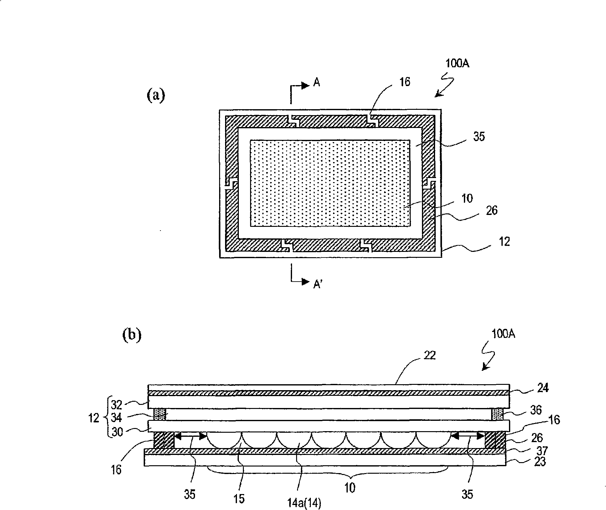
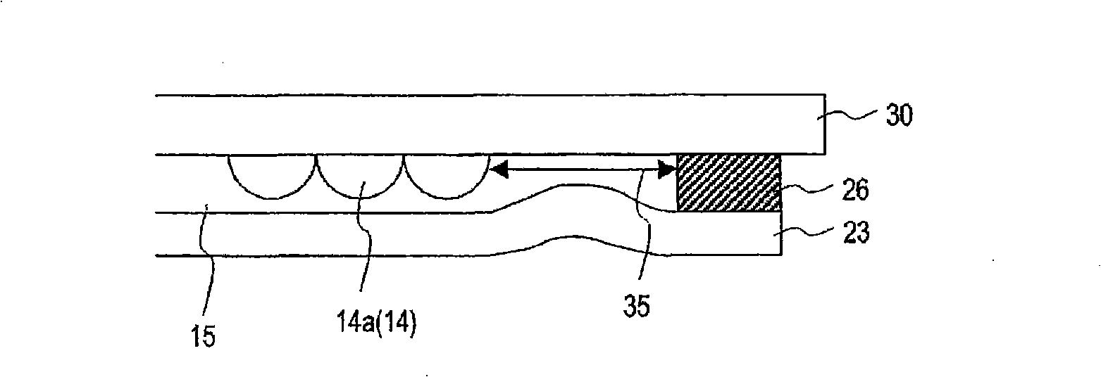
[0081] figure 1 It is a diagram schematically showing the configuration of a liquid crystal display panel 100A with a microlens array (hereinafter, may be simply referred to as the liquid crystal display panel 100A) according to this embodiment. figure 1 (a) shows a plan view of the liquid crystal display panel 100A, figure 1 (b) means figure 1 The structure of the liquid crystal display panel 100A in the A-A' section of (a).

[0082] As shown in the drawing, a liquid crystal display panel 100A of this embodiment includes: a liquid crystal display panel (also referred to as a “liquid crystal cell”) 12 having a plurality of pixels arranged in a matrix; figure 1 The microlens array 14 that comprises a plurality of microlenses 14a on the lower side of (b); the support body 26 that is a...


PUM

PropertyMeasurementUnit
heightaaaaaaaaaa
refractive indexaaaaaaaaaa

Abstract

Provided is a liquid crystal display panel having a microlens array, which does not easily generate deformation, peeling and the like of an optical film and has excellent display quality. A liquid crystal display panel (100A) having a microlens array is provided with a microlens array (14) arranged on the light incoming side of a liquid crystal display panel (12); a supporting body (26) arranged to surround the microlens array (14) on the light incoming side of the liquid crystal display panel (12); and an optical film (23) adhered to the liquid crystal display panel (12) through the supporting body (26). A gap (15) is formed between the microlens array (14) and the optical film (23). At least one ventilation hole (16) for connecting a space outside the supporting body (26) with the gap (15) is formed on the supporting body (26). When the ventilation hole (16) is viewed vertically to the surface of the liquid crystal display panel (12), the ventilation hole extends by being bent or in a direction diagonal to the inner surface of the supporting body (26).

Description

technical field [0001] The invention relates to a liquid crystal display panel and a liquid crystal display device, in particular to a liquid crystal display panel and a liquid crystal display device with a microlens array. Background technique [0002] In recent years, liquid crystal display devices have been widely used as display devices for monitors, projectors, portable information terminals, mobile phones, and the like. In general, a liquid crystal display device changes the transmittance (or reflectance) of the liquid crystal display panel by using a driving signal, modulates the intensity of light from a light source irradiating the liquid crystal display panel, and displays images and characters. As liquid crystal display devices, there are direct-view display devices that directly observe images displayed on a liquid crystal display panel, and projection display devices that enlarge and project images displayed on a liquid crystal display panel on a screen using a ...

Claims


Application Information

Patent Timeline
Patent Type & Authority Applications(China)
IPC IPC(8): G02F1/1335G02F1/13357G09F9/00
CPCG02F1/133526G02F2201/36
Inventor 村尾岳洋小瀬川征志臼仓奈留
Owner SHARP KK
Why Eureka
Try Eureka