Optical symbol, article to which the optical symbol is attached, method for attaching optical symbol to article, and optical recognition code recognizing method

An identification code, optical technology, applied to record carriers, instruments, electromagnetic radiation induction used by machines, etc., can solve problems such as decoding difficulties

Inactive Publication Date: 2009-08-26
B CORE INC
View PDF9 Cites 2 Cited by
  • Summary
  • Abstract
  • Description
  • Claims
  • Application Information

AI Technical Summary

Problems solved by technology

[0022] Therefore, the idea of ​​selecting a one-dimensional barcode is simpler than that of a two-dimensional barcode, but in the case of one-dimensional, a fixed width (length of thick and thin bars) is required in the "mark pattern" of the barcode, and when the barcode is thin or curved Wait, it will be very difficult to decode

Method used


Image

  • Optical symbol, article to which the optical symbol is attached, method for attaching optical symbol to article, and optical recognition code recognizing method
  • Optical symbol, article to which the optical symbol is attached, method for attaching optical symbol to article, and optical recognition code recognizing method
  • Optical symbol, article to which the optical symbol is attached, method for attaching optical symbol to article, and optical recognition code recognizing method

Examples


Embodiment approach 2

[0263] "Implementation Mode Two"

[0264] Next, a second preferred embodiment of the present invention will be described with reference to the drawings.

[0265] Section 2-11.5D Summary of Color Bit Code

[0266] First, the outline of the 1.5D color bit code developed by the inventors of the present application will be described. The 1.5D color bit code described here is an example using 3 colors as marking colors. For example, there are three colors of R (red), G (green), and B (blue) (C, M, and Y are also possible). Also, an example in which W (white) is shown as the still chromatic color constituting the still area is shown.

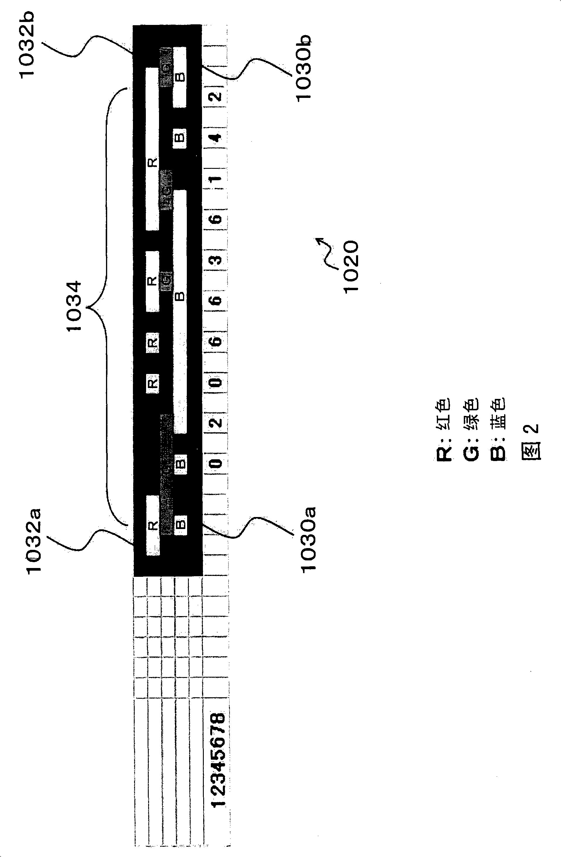
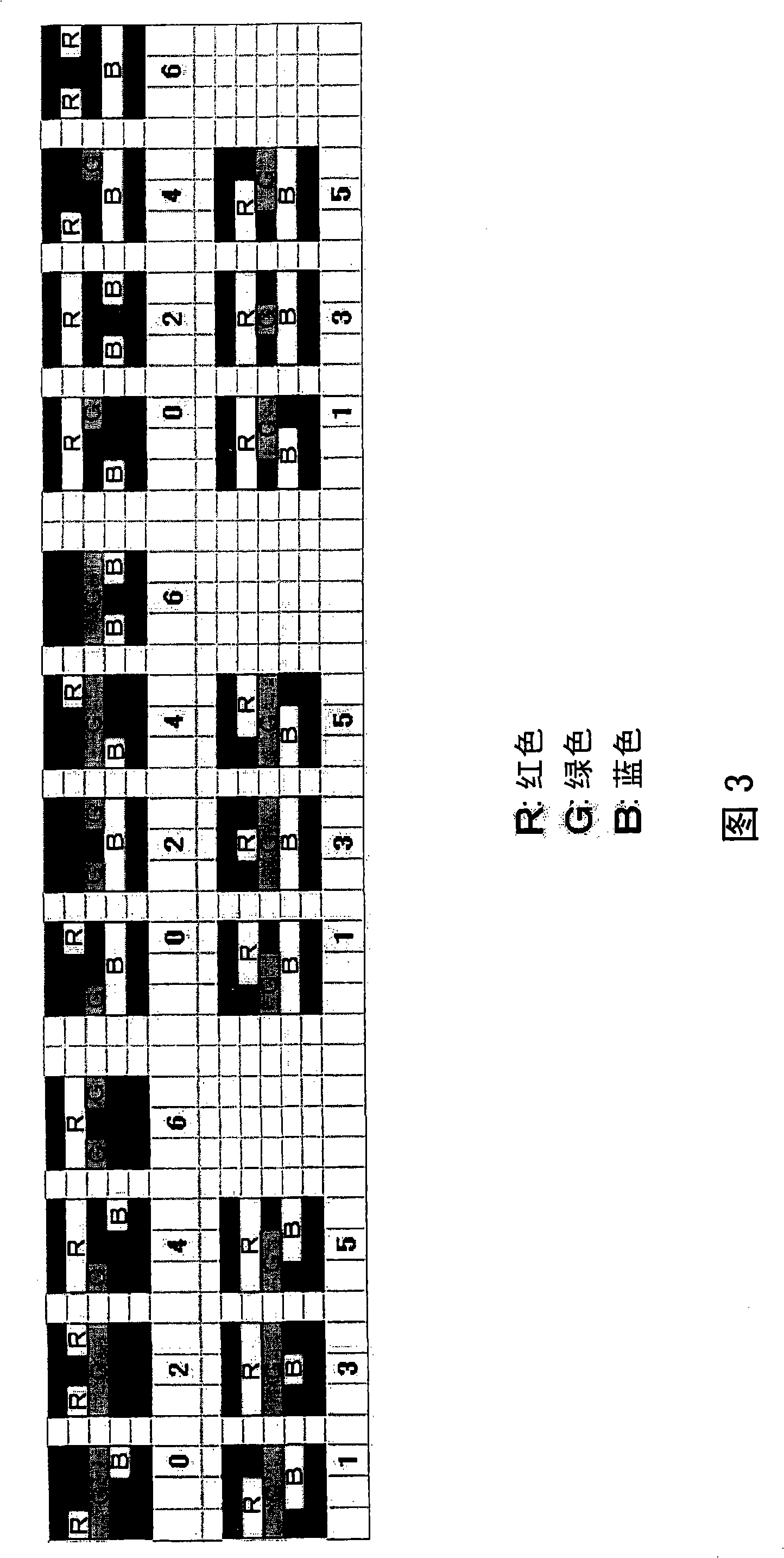
[0267] In the 1.5D color bit code, three lines of different colors are arranged in parallel and approximately equally spaced to form a column.

[0268] Each of the three columns is interrupted somewhere in the middle, and the interrupted part is a color corresponding to the still area (that is, W). The interrupted part of each column including bo...

Embodiment approach 3

[0367] "Implementation Mode Three"

[0368] Next, a third preferred embodiment of the present invention will be described with reference to the drawings.

[0369] Section 3-11.5D Summary of Color Bit Code

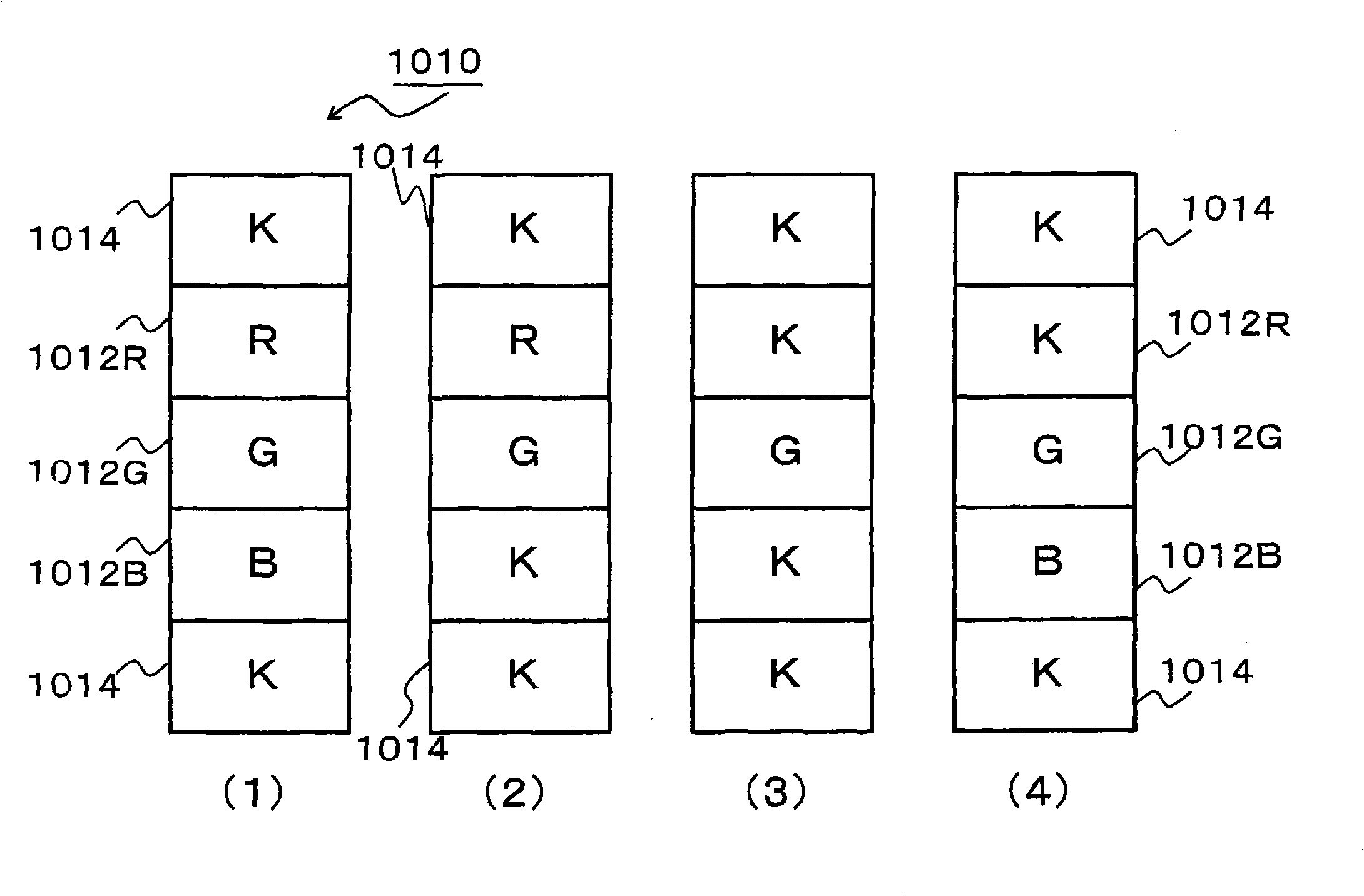
[0370] First, the outline of the 1.5D color bit code developed by the inventors of the present application will be described. The 1.5D color bit code described here is an example using 3 colors as marking colors. For example, there are three colors of R (red), G (red), and B (red) (C, M, and Y are also possible). Also, an example is shown in which the still color constituting the still area is K (black).

[0371] First, in the 1.5D color bit code, three lines of different colors are arranged in parallel and approximately equally spaced to form a column. Each of the three columns is interrupted somewhere in the middle, and the interrupted part is the color corresponding to the still area (that is, K (black)). The interrupted part of each column including both ends is re...

Embodiment 3-4-1

[0407] "Example 3-4-1"

[0408] And, when only one of the variable "0 and 1", "4 and 5" numbers is included in the 10-digit number,

[0409] Research (example) 22222122223232066232 and so on.

[0410] In this case, there is generally only one pattern that is easily changed (variable side). For the example mentioned,

[0411] 2222212222 easy to change

[0412] ↓

[0413] 2222202222

[0414] 3232066232 easy to change

[0415] ↓

[0416] 3232166232

[0417] Therefore, as the check number, it is only necessary to add a numerical value (for example, 0, 1, etc.) that obtains two types of values.

[0418] Since only two types of values ​​are required, it is typically preferable to add parity (parity check) as the CD, for example. And, if the parity is calculated and its value is different from CD, it is judged that a change (misread) has occurred as described above.

[0419] However, in order to simplify the description, the difficulty of changing the test number itse...


PUM


Abstract

It is possible to provide a code using an optical symbol which can be read with a high accuracy even under an environment of a low printing accuracy including printing on an article which can be easily deformed. Cells are arranged in a linear shape and particular data is indicated by a state of element in each of the cells (whether the element is colored). Especially a particular color is fixed to each of the elements and it is possible to use the two states whether the color is attached or not. This state can express the data. Accordingly, it is possible to realize a code system capable of reading data if the element sequence continuity and the form (topology) as the linear state are maintained.

Description

technical field [0001] The present invention relates to an optical code for information processing added to an article. In particular, it relates to an optical symbol used in the optical code, a method of attaching the optical symbol to an article, and a decoding method. [0002] Furthermore, the present invention relates to a method for selecting an optical identification code. In particular, it relates to an identification (selection) method of a new optical identification code (called a 1.5D color bit code (Japanese Patent Application No. 2006-196548)) invented by the inventors of the present application. [0003] Furthermore, the present invention relates to a verification method of an optical identification code. In particular, it relates to an inspection method of a new optical identification code (called a 1.5D color bit code (Japanese Patent Application No. 2006-196548)) invented by the inventors of the present application. Background technique [0004] (backgroun...

Claims


Application Information

Patent Timeline
Patent Type & Authority Applications(China)
IPC IPC(8): G06K19/06G06K7/12
Inventor 木村昭辉松田昌幸汉人邦夫
Owner B CORE INC
Why Eureka
Try Eureka