

Machining unit for a milling and drilling machine
A technology of mechanical processing, drilling and milling machines, which is applied in the direction of milling machines, milling machine equipment, metal processing equipment, etc., and can solve problems such as chip damage and collision
- Summary
- Abstract
- Description
- Claims
- Application Information
AI Technical Summary
Problems solved by technology
Method used
Image

Examples
Embodiment Construction
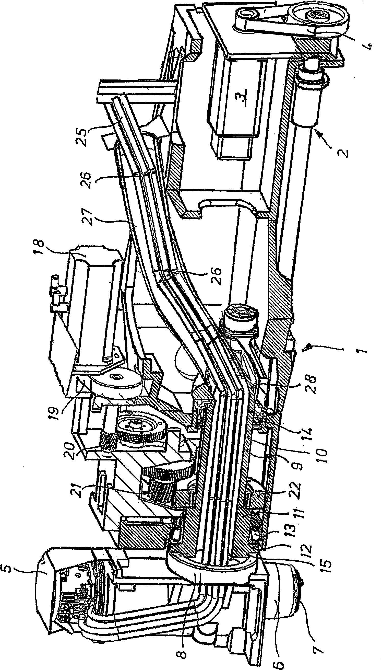
[0009] Hereinafter, embodiments of the present invention will be described in detail with reference to the accompanying drawings, in which a machining unit for a drilling and milling machine is schematically illustrated in longitudinal section.
[0010] The illustrated machining unit comprises a spindle housing 1 which is arranged on the assembly of the drilling and milling machine via guide rails (not shown) and is guided and slidable in the longitudinal direction. The spindle drive 2 is used for the longitudinal movement of the machining unit, which in this case contains a so-called recirculating ball screw driven by an electric motor 3 via a belt drive 4 . At the left end of the spindle housing 1 in the figure, a vertical milling head 5 is mounted and rotatable about a horizontal axis into selectable operating positions. A work spindle 6 is supported in this milling head 5 , which is driven by an internal motor and has a tool-holding clamp 7 at its lower end.
[0011] In t...
PUM
 Abstract
Description
Claims
Application Information