
Vibration-damping and locking integrating device of chassis suspension fork of vehicle

A chassis and suspension technology, applied in suspension, elastic suspension, vehicle parts, etc., can solve the problems of complex structure, large chassis space, failure of mechanical locking device, etc., to achieve high action sensitivity, simple working process, occupancy small space effect

Inactive Publication Date: 2009-09-02
CHONGQING UNIV +1
View PDF1 Cites 2 Cited by
  • Summary
  • Abstract
  • Description
  • Claims
  • Application Information

AI Technical Summary

Problems solved by technology

The main disadvantages of this device are: 1. It is an auxiliary mechanical locking device that is increased by means of the existing shock absorber function. 2. The device needs to be combined with the existing shock absorber of the vehicle to realize the locking action, and the inner cavity of the cylinder barrel of the existing shock absorber is fixed on the piston rod. The piston is divided into upper and lower chambers, and the upper and lower chambers of the cylinder are connected through the expansion valve and the flow valve installed in the piston on both sides of the piston rod, and the upper and lower chambers of the cylinder are connected only by the friction force of the brake band, and then As a result, the locking mechanism cannot realize the two-way rigid locking of the vehicle chassis suspension under heavy load and high pressure conditions; 3. The locking device itself does not have the function of vibration reduction, and cannot work independently from the original shock absorber at all; 4. .Only limited to vehicles with air actuators, and only limited to parking brake conditions, the scope of application is limited, and the locking ability generated by air actuators is limited; 5. The shock absorber is separated from the locking device, Take up a lot of chassis space

Method used


Image

  • Vibration-damping and locking integrating device of chassis suspension fork of vehicle
  • Vibration-damping and locking integrating device of chassis suspension fork of vehicle
  • Vibration-damping and locking integrating device of chassis suspension fork of vehicle

Examples


Embodiment

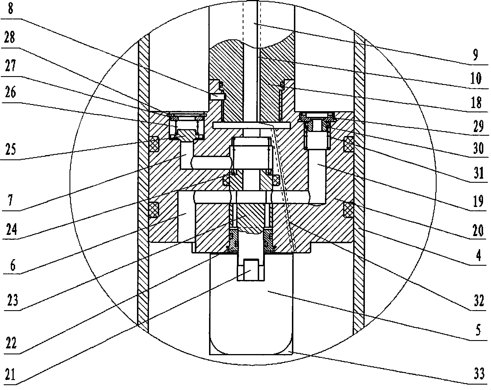
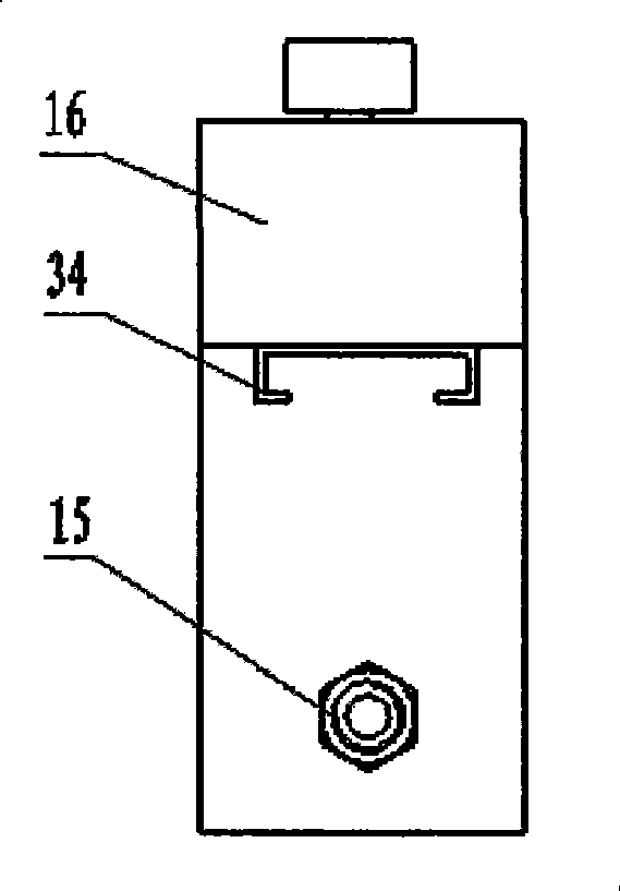
[0025] Such as Figure 1-3 Shown: an integrated vehicle chassis suspension vibration damping and locking device, mainly including a piston rod 18, a cylinder 4, a piston 20, a lock valve 23, a DC electromagnet 5, an oil storage tank 16, and the like. The end cover at the lower end of the cylinder 4 is fixedly connected with an adapter 1 with lifting lugs through the bushing 2 and the pin shaft 3, and the lifting lugs are fixed on the axle through the pin shafts and pins. The piston 20 of the piston rod 18, the piston 18 divides the inner cavity of the cylinder barrel 4 into two upper and lower cavities that are not communicated with each other. The top of the cylinder barrel 4 is equipped with a guide seat 12, the guide seat 12 is tightly connected with the cylinder barrel 4 through threads, and a sealing ring is respectively arranged between the guide seat 12 and the cylinder barrel 4, the guide seat 12 and the piston rod 18, for Prevent oil leakage during work. A dust-proo...


PUM


Abstract

The invention relates to a vibration-damping and locking integrating device of a chassis suspension fork of a vehicle, in particular to a vibration-damping and locking device of a chassis suspension fork of a vehicle. The vibration-damping and locking device mainly comprises a piston rod, a cylinder, a piston, a lock valve, a DC electromagnet, an oil tank, and the like. The device is arranged between a vehicle body and an axle, has the characteristics of compact structure, less space occupation, convenient installation, high sensitivity and reliability, low cost, and the like, can complete the bilateral rigid locking and vibration damping of the chassis suspension fork of a vehicle and can adapt to the severe atmosphere of a vehicle chassis. The device can be widely used as a vibration-damping and locking device of the chassis suspension forks of various vehicles, is suitable for vehicles with compact structural space, and particularly suitable for being used as the vibration-damping and locking devices of the chassis suspension forks of special vehicles, special purpose vehicles and heavy-duty vehicles, thereby satisfying the special use requirements of the vehicles.

Description

1. Technical field [0001] The invention belongs to the technical field of vehicle chassis suspension structures, and in particular relates to a vibration damping and locking device for vehicle chassis suspensions. 2. Background technology [0002] As a system to support the body and improve ride comfort, the automobile suspension system plays an important role in the chassis structure of the automobile. In order to prevent the vehicle suspension from bouncing, realizing the two-way rigid self-locking of the chassis suspension will increase the use requirements of the vehicle. In some special vehicles and special vehicles, such as wheeled cranes, aerial work vehicles, etc., under some working conditions, it is necessary to realize the two-way rigid self-locking of the chassis suspension. Except for the oil-pneumatic suspension system, other types of suspension systems are difficult. With this two-way self-locking function. However, the use of oil-pneumatic suspension to rea...

Claims


Application Information

Patent Timeline
IPC IPC(8): B60G17/005B60G13/08
Inventor 邓兆祥曹友强王洪春阮德玉唐健李军牟科梁栋
Owner CHONGQING UNIV
Learn More