Crystal growth furnace body structure with emergency decompression arrangement

A technology of crystal growth furnace and pressure relief, applied in furnaces, muffle furnaces, cooking furnaces, etc., can solve the problems of difficult discharge of pressure, explosion of furnace body, and insufficient circumferential extension.

Inactive Publication Date: 2011-07-20
GREEN ENERGY TECH
View PDF0 Cites 0 Cited by
  • Summary
  • Abstract
  • Description
  • Claims
  • Application Information

AI Technical Summary

Problems solved by technology

Since the crystal growth furnace 91 is all installed in the factory building 9, the noise and dust pollution generated during its operation will have adverse effects on the health of the operators after long-term accumulation
[0003] What's more, the device for releasing pressure in the known crystal growth furnace 91 is either lacking or not sufficiently comprehensive. Once abnormal pressure occurs in the crystal growth furnace 91 furnace, for example, the crucible containing the molten silicon slurry bursts and the silicon slurry leaks. flow, and the released silicon slurry remelts through the furnace wall and reacts with the cooling pure water to generate a large amount of gas, which instantly generates high pressure in the furnace, as shown in Figure 1, the respective pressure relief pipes 911 of the crystal growth furnace 91 They are respectively connected to the public pressure relief pipe 98. Due to the long pipeline and large damping, the pressure is not easy to discharge or it is too late to release the pressure in an instant, causing the furnace body to burst, and because the crystal growth furnace 91 and the personnel control room 92 are both set in the same airtight factory building 9 , will inevitably endanger the safety of operators, and unavoidable industrial safety incidents will occur

Method used


Image

  • Crystal growth furnace body structure with emergency decompression arrangement
  • Crystal growth furnace body structure with emergency decompression arrangement
  • Crystal growth furnace body structure with emergency decompression arrangement

Examples


Embodiment Construction

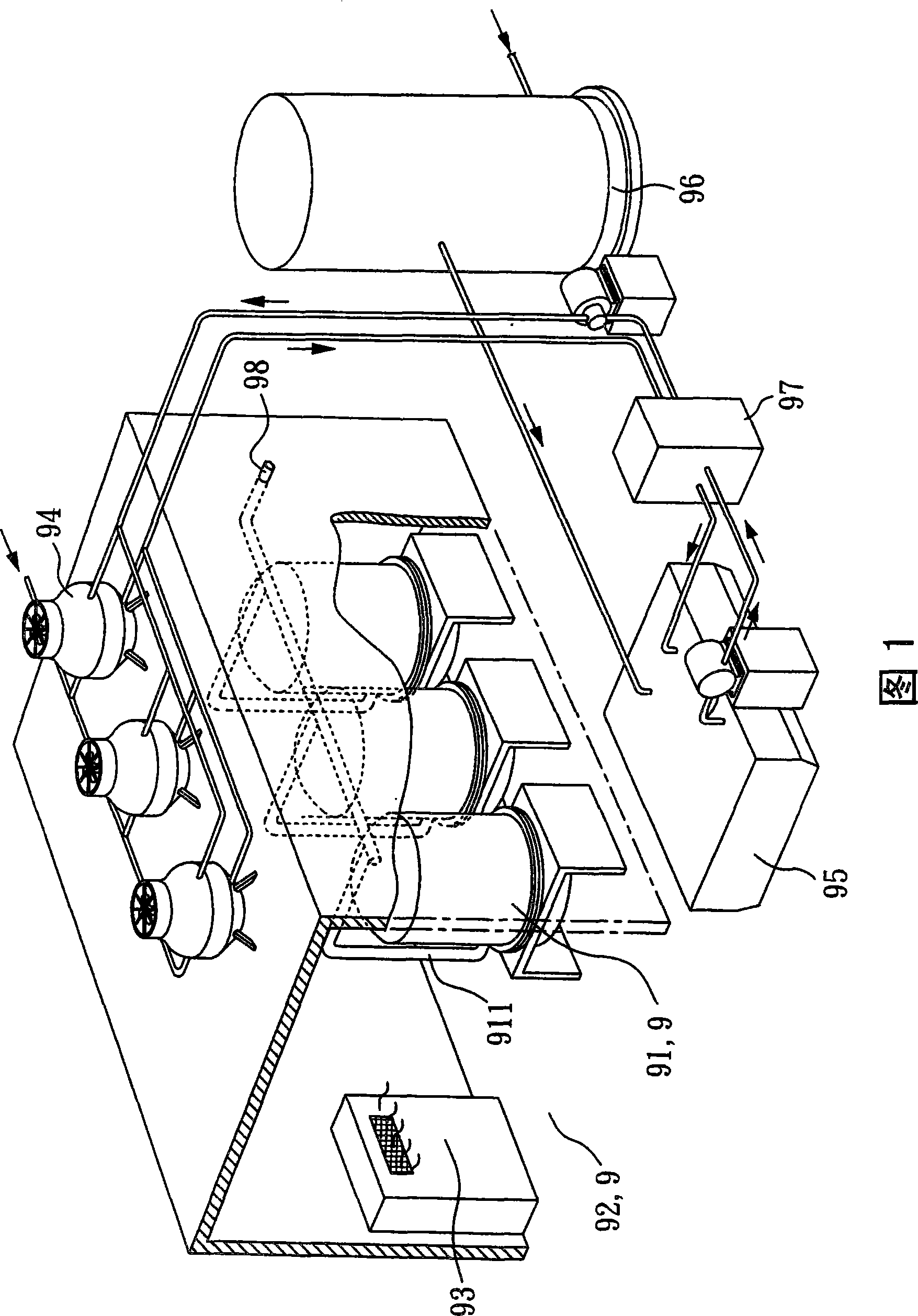
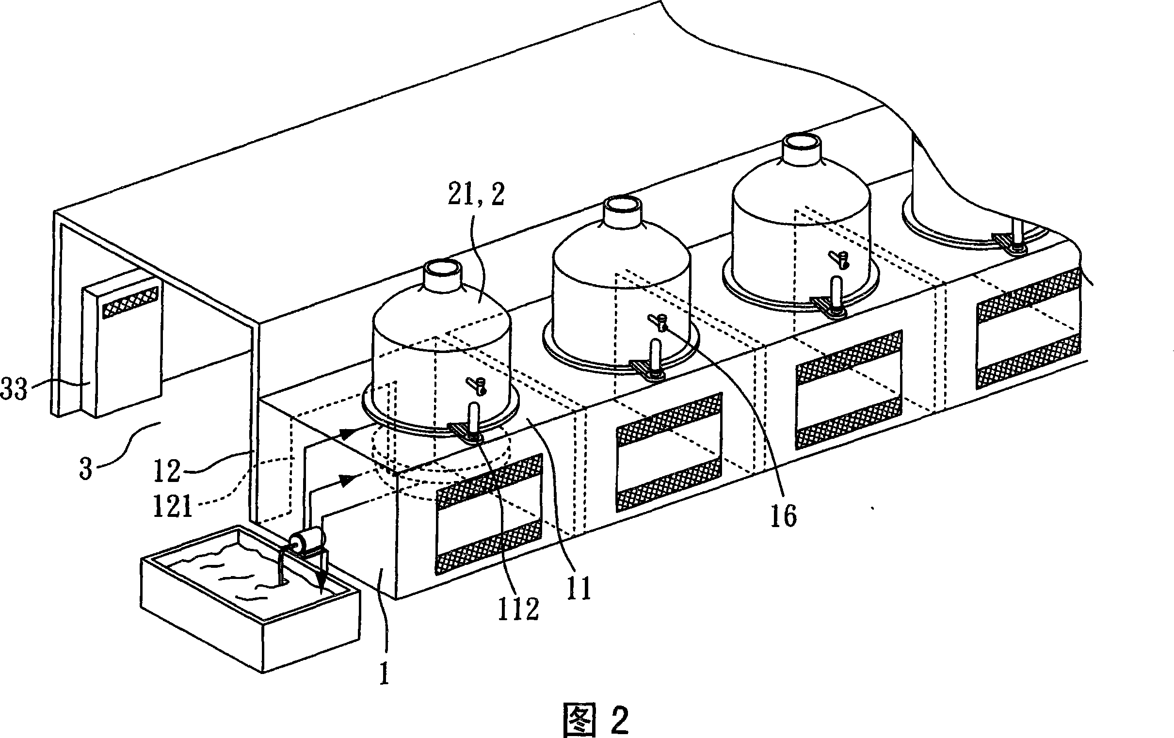
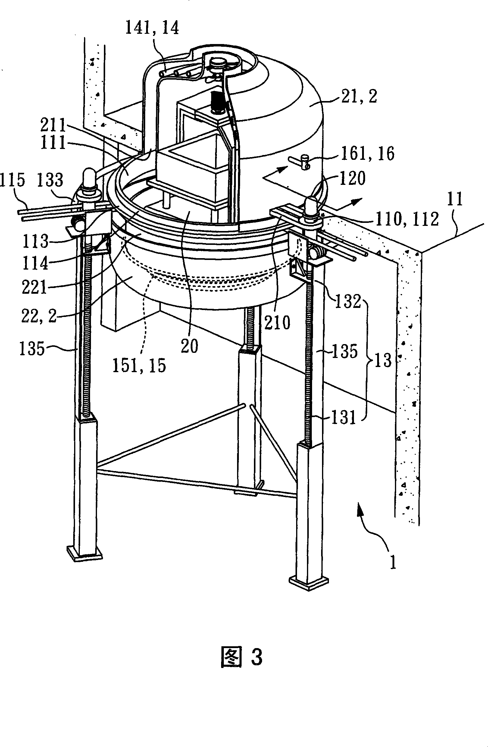
[0055] Please refer to FIG. 2 and FIG. 3 together. FIG. 2 is a system structure diagram of a preferred embodiment of the present invention, and FIG. 3 is a perspective view of a preferred embodiment of the present invention. As shown in the figure, this embodiment is a crystal growth furnace structure with an emergency pressure relief configuration, including an isolation chamber 1 and a furnace upper chamber 21 .

[0056] As shown in Figure 2 and Figure 3, the isolation chamber 1 includes a top plate 11, the top plate 11 includes a through opening 111, and at least one first guide 112, at least one first guide 112 protrudes above the top plate 11 and Adjacent to the opening 111 , the isolation chamber 1 is provided with a furnace bottom cover 22 , and the furnace bottom cover 22 is provided with an upper opening 221 . The upper opening 221 is upwardly corresponding to the opening 111 of the top plate 11 .

[0057] Please refer to FIG. 4 and FIG. 3 at the same time. FIG. 4 is ...


PUM


Abstract

The invention relates to a crystal growth furnace body structure with emergency decompression arrangement. The lower opening of an upper furnace chamber covers the opening of the top plate of an isolaThe invention relates to a crystal growth furnace body structure with emergency decompression arrangement. The lower opening of an upper furnace chamber covers the opening of the top plate of an isolation chamber correspondingly, and three positioning rings which are convexly arranged at equal angles on the outside of the upper furnace chamber are respectively movably sheathed on three upward lugstion chamber correspondingly, and three positioning rings which are convexly arranged at equal angles on the outside of the upper furnace chamber are respectively movably sheathed on three upward lugs arranged on the top plate and can be guided to move up and down. If the air pressure in a crystal growth furnace formed by the closing of the upper furnace chamber and a bottom furnace cover is overharranged on the top plate and can be guided to move up and down. If the air pressure in a crystal growth furnace formed by the closing of the upper furnace chamber and a bottom furnace cover is overhigh, when the weight of the upper furnace chamber is upwardly overcome so as to lift the upper furnace chamber, the upper furnace chamber is slightly opened upwards along with the guiding of the upwarigh, when the weight of the upper furnace chamber is upwardly overcome so as to lift the upper furnace chamber, the upper furnace chamber is slightly opened upwards along with the guiding of the upward lugs by depending on the positioning ring so as to release the internal air instantly, subsequently, the upper furnace chamber drops again due to the own weight to cover the opening. If a cross decod lugs by depending on the positioning ring so as to release the internal air instantly, subsequently, the upper furnace chamber drops again due to the own weight to cover the opening. If a cross decompression tube is added on the upper furnace chamber, low pressure can be moderately released, therefore the structure has the function of duel decompressing protection and can fully prevent the occurmpression tube is added on the upper furnace chamber, low pressure can be moderately released, therefore the structure has the function of duel decompressing protection and can fully prevent the occurrence of industrial safety accident of furnace body explosion.rence of industrial safety accident of furnace body explosion.

Description

technical field [0001] The invention relates to a structure of a crystal growth furnace, in particular to a structure of a crystal growth furnace suitable for emergency pressure relief configuration. Background technique [0002] Please refer to FIG. 1 , which is a structural diagram of a known crystal growth furnace system. As shown in the figure, multiple crystal growth furnaces 91 and personnel control rooms 92 are all set in the same airtight factory building 9 . Since the crystal growth furnaces 91 are all installed in the factory building 9, the noise and dust pollution generated during operation will have adverse effects on the health of the operators after long-term accumulation. [0003] What's more, the device for releasing pressure in the known crystal growth furnace 91 is either lacking or not sufficiently comprehensive. Once abnormal pressure occurs in the crystal growth furnace 91 furnace, for example, the crucible containing the molten silicon slurry bursts a...

Claims


Application Information

Patent Timeline
Patent Type & Authority Patents(China)
IPC IPC(8): F27B5/06C30B29/06F27B14/08C30B35/00F27B14/04F27B5/04
Inventor 吕秀正林和龙
Owner GREEN ENERGY TECH
Why Eureka
Try Eureka