Printed circuit board apparatus

A printed circuit board and printed circuit technology, applied in the direction of electrical components, support structure installation, electrical equipment construction parts, etc., can solve the problems of small anti-vibration ability and insufficient mechanical strength of printed circuit board devices, and achieve anti-vibration performance The effect of improving, strength and mechanical stability is reduced

Inactive Publication Date: 2009-09-02
ROBERT BOSCH GMBH
View PDF0 Cites 12 Cited by
  • Summary
  • Abstract
  • Description
  • Claims
  • Application Information

AI Technical Summary

Problems solved by technology

Disadvantages in this known printed circuit board arrangement are that on the one hand the printed circuit board arrangement does not have sufficient mechanical strength and on the other hand has a low resistance to vibrations
As in the other aforementioned known printed circuit board arrangements, the printed circuit board 6 does not act as a reinforcement with respect to the entire housing

Method used


Image

  • Printed circuit board apparatus
  • Printed circuit board apparatus

Examples


Embodiment Construction

[0019] In the figures, identical components and components having the same function are designated with the same reference numerals.

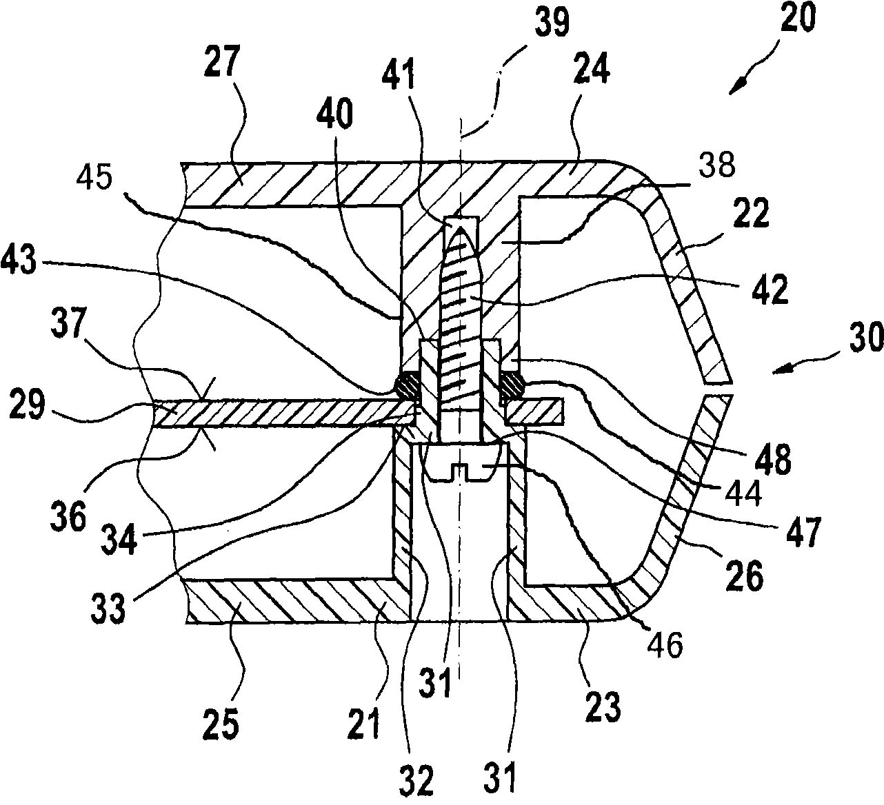
[0020] exist figure 1 A printed circuit board assembly 20 (printed circuit board holding device) is shown in . It comprises two housing parts constructed as plastic injection-molded parts, namely a first housing part 21 located below in the drawing and an opposite second housing part 22 arranged above in the drawing. The two housing parts 21 , 22 are designed as housing shells and comprise a first outer wall 23 and a second outer wall 24 . The first outer wall 23 is formed by a flat bottom wall section 25 and a peripheral first side wall section 26 adjoining it on the edge side, which extends at an angle to the first bottom wall section 25 . Similarly, the second outer wall 24 is formed by a second base wall section 27 and a second side wall section 28 extending at an angle thereto in the direction of the first side wall section 26 .

[002...


PUM


Abstract

The invention relates to a printed circuit board apparatus(20), comprising a housing(30) which includes a first housing part(21) and at least a second housing part(22); the second housing part is fixed on the first housing part(21) by at least a fixing component(42); wherein a printed circuit board(29) is axially clamped between a first support section(31) of the first housing part(21) and a second support section(38) of the second housing part(22). According to the invention, the fixing component(42) is arranged to act on the two support section(31,38).

Description

technical field [0001] The invention relates to a printed circuit board arrangement according to the preamble of claim 1 . Background technique [0002] The fixing of printed circuit boards in multi-part housings is currently achieved in various ways. For example, it is known to fix a printed circuit board in one of the housing parts by means of a snap connection. Tolerance problems in this type of fastening often lead to too loose a printed circuit board carrier, which does not have sufficient mechanical strength for shock loads, for example due to falling from a critical point. In addition, such snap connections have little vibration resistance, especially when heavy electronic components are mounted on the printed circuit board. As a result, the printed circuit board can resonate at unfavorable natural frequencies and be damaged as a result. [0003] In addition to snap connections, screw connections are also known, wherein in this case the printed circuit board is pas...

Claims


Application Information

Patent Timeline
Patent Type & Authority Applications(China)
IPC IPC(8): H05K7/14
CPCH05K7/142
Inventor M·雷曼
Owner ROBERT BOSCH GMBH
Why Eureka
Try Eureka