Supercharge Your Innovation With Domain-Expert AI Agents!

Insert part, gas lens with the insert part and welding torch with the gas lens

A technology of inserting components, gas, applied in the direction of manufacturing tools, electrode characteristics, welding equipment, etc., to achieve the effect of operation improvement

Active Publication Date: 2011-12-28
FRONIUS INTERNATIONAL GMBH
View PDF0 Cites 0 Cited by
  • Summary
  • Abstract
  • Description
  • Claims
  • Application Information

AI Technical Summary

Problems solved by technology

Also, in the prior art, several gas lens filters had to be used to generate a suitable backflow

Method used


Image

  • Insert part, gas lens with the insert part and welding torch with the gas lens
  • Insert part, gas lens with the insert part and welding torch with the gas lens
  • Insert part, gas lens with the insert part and welding torch with the gas lens

Examples


Embodiment Construction

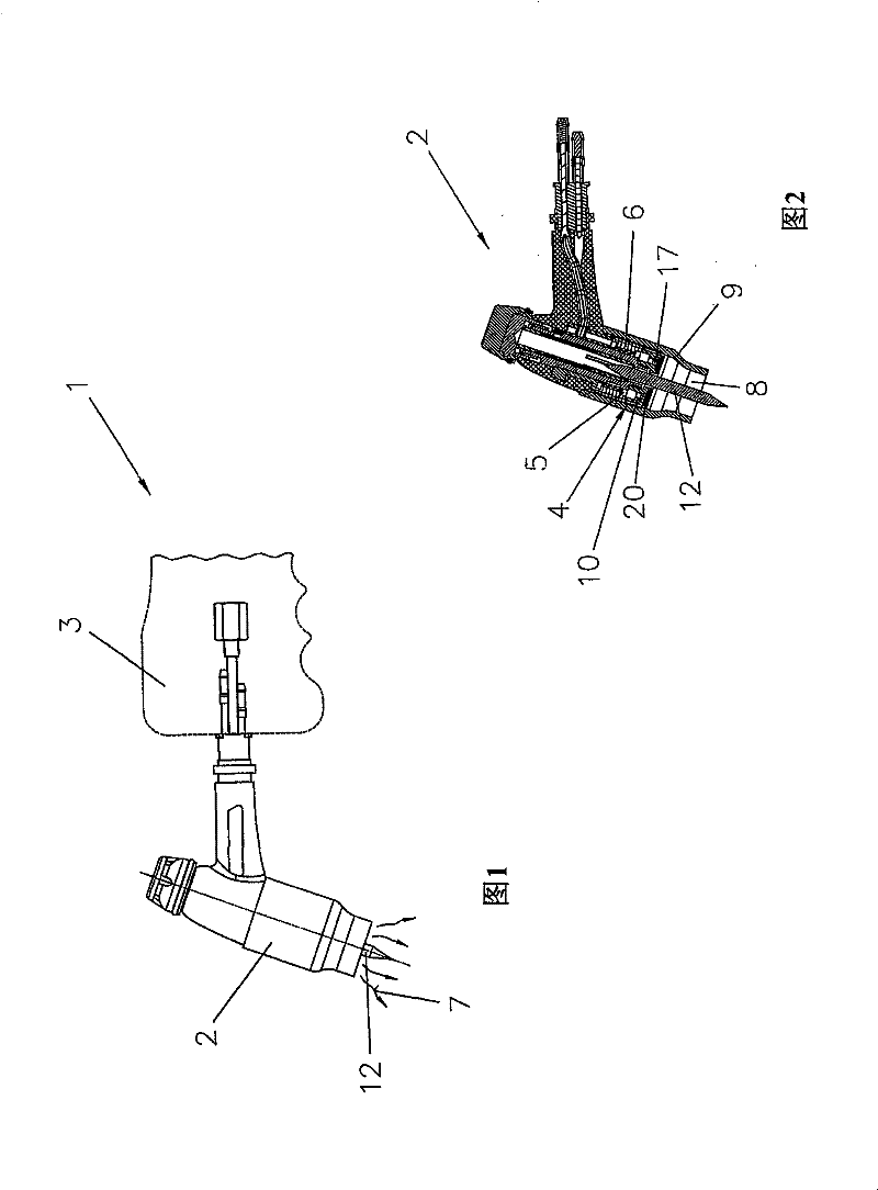
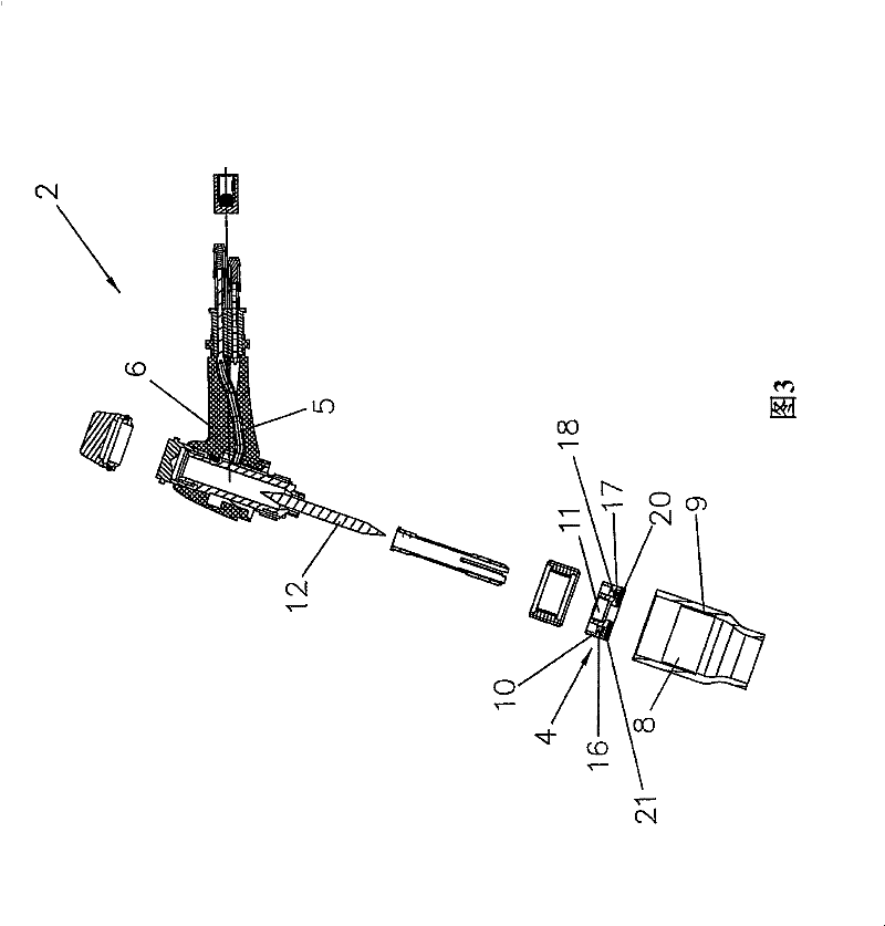
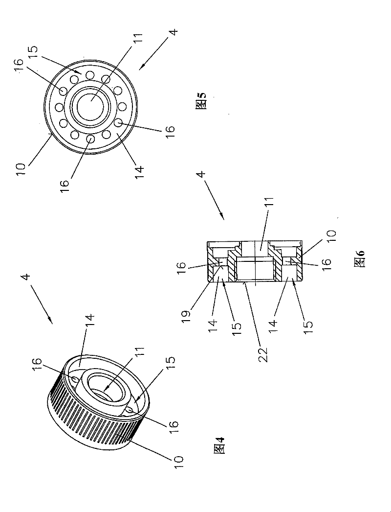
[0028] Figure 1 to Figure 10 A WIG / TIG torch 1 is shown. The welding torch 1 includes a welding torch body 2 and a welding torch handle 3 . Here, the structures of the various components of the welding torch 1 correspond to those in the prior art, so these components and their functions will not be described in detail.

[0029] The invention is a detailed solution for the gas lens 4 provided in the torch body 2 for distributing the gas 7 fed through the gas supply channel 5 in the base 6 . The gas 7 fed through the base 6 flows from the base 6 into the gas lens 4 and will then be dispersed through the cross-section of the gas lens 4 . This allows an optimum distribution of the gas in the gas nozzle 9 as the gas 7 flows out of the gas lens 4 and into the interior 8 of the gas nozzle 9 . It is critical here that the size of the gas lens 4 be as small as possible, as this reduces the overall size of the welding torch 1 and greatly improves the handling of the welding torch 1 ...


PUM


Abstract

For a WIG / TIG welding torch, gas distribution across a cross-section of the gas lens and / or the gas nozzle, is improved and as small a size and as low a weight of the components as possible can be achieved, when an insertion element with a bore in the center through which an electrode is to be guided is arranged, with fan-shaped flow elements being positioned around the bore and twisted relative to the plane of the bore so as to provide for radial deviation of a gas flowing therethrough. The gas lens consists of a base body having a gas distribution channel with at least one gas-lens filter, with an above-described insertion element being arranged in the gas-distribution channel, and with a gas-lens filter, seen in the out-flow direction of the gas, being arranged downstream of the insertion element.

Description

technical field [0001] The invention relates to an insert part for a gas lens for a WIG / TIG welding torch, a gas lens for a WIG / TIG welding torch and a WIG / TIG welding torch according to claims 1 , 2 and 5 . Background technique [0002] WIG / TIG welding torches are known in the prior art, in which a gas lens is inserted into the torch body, a gas lens filter being provided in the gas distribution space of the torch. The gas lens filters are always spaced apart from each other, allowing a corresponding diffusion of gas in the cavity between the base body of the gas lens and the gas lens filter and in the cavity between the gas lens filters. [0003] A disadvantage here is that correspondingly larger cavities have to be provided between the gas lens filters in order to allow good gas distribution, which is why the dimensions of the gas lenses have to be correspondingly larger. Also, in the prior art, several gas lens filters had to be used to generate a suitable backflow. In...

Claims


Application Information

Patent Timeline
Patent Type & Authority Patents(China)
IPC IPC(8): B23K9/29
CPCB23K9/296B23K9/167B23K9/29B23K9/24B23K9/291B23K9/285
Inventor 约亨·费斯尔梅莱涅·盖贝什梅尔约瑟夫·莱布
Owner FRONIUS INTERNATIONAL GMBH
Features
  • R&D
  • Intellectual Property
  • Life Sciences
  • Materials
  • Tech Scout
  • Unparalleled Data Quality
  • Higher Quality Content
  • 60% Fewer Hallucinations
Learn More