
Injection moulding device comprising needle valve nozzles in a back-to-back arrangement

A technology of injection molding equipment and nozzles, which is applied in the field of injection molding equipment, can solve problems such as piston guidance and piston unit sealing, and achieve the effect of saving space

Inactive Publication Date: 2009-09-02
GUENTHER HEISSKANALTECHNIK GMBH
View PDF1 Cites 4 Cited by
  • Summary
  • Abstract
  • Description
  • Claims
  • Application Information

AI Technical Summary

Problems solved by technology

Although this results in a rather compact construction of the injection molding system, problems with the sealing of the piston unit and piston guidance can also arise here due to the distribution plate, which heats up strongly during operation of the injection molding system.

Method used


Image

  • Injection moulding device comprising needle valve nozzles in a back-to-back arrangement
  • Injection moulding device comprising needle valve nozzles in a back-to-back arrangement
  • Injection moulding device comprising needle valve nozzles in a back-to-back arrangement

Examples


Embodiment Construction

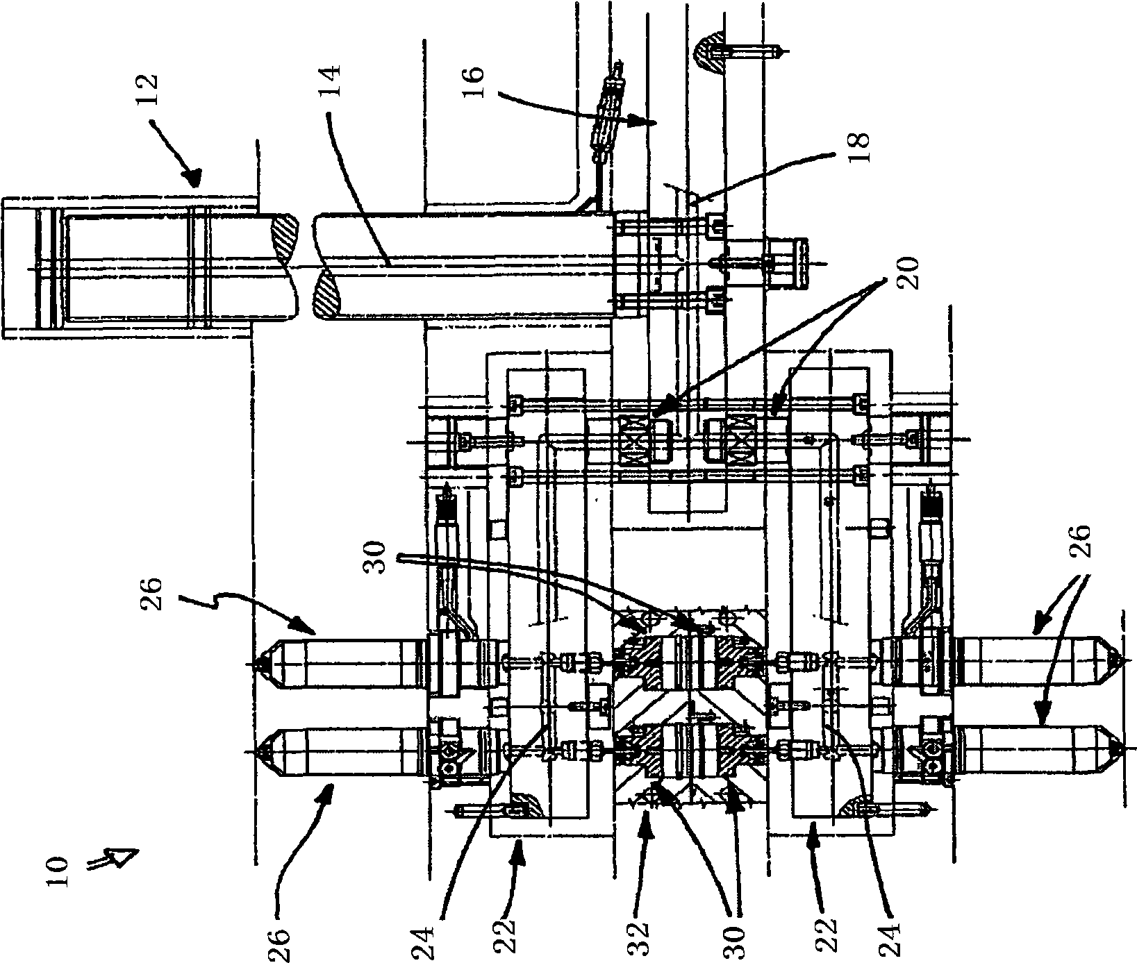
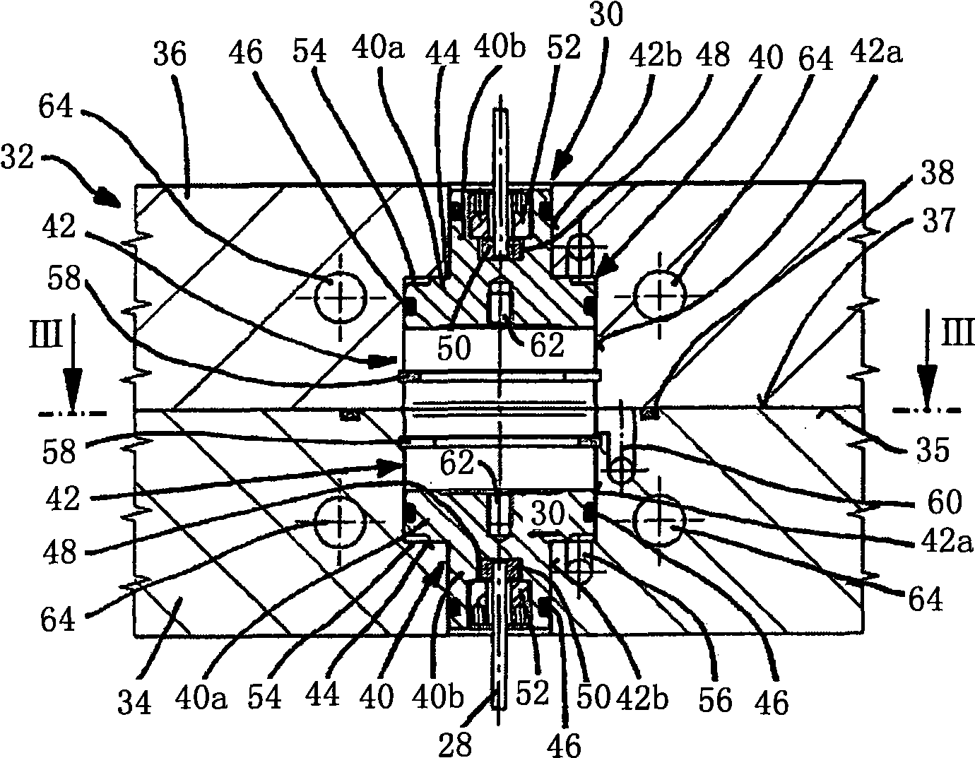
[0027] figure 1 A partial cross-sectional view of the first embodiment of the injection molding apparatus 10 according to the present invention is shown. The injection molding device 10 includes a fluid inflow nozzle 12 having a central hole 14 through which the material to be processed, such as plastic melt, is conveyed to the main distribution plate 16 during the operation of the injection molding device 10. A flow channel 18 is formed in the main distribution plate 16, and the flow channel 18 continues to guide the fluid through the joint elements 20 arranged on the secondary distribution plate 22 below and above the main distribution plate 16.

[0028] In the sub-distribution plate 22, the fluid flows through the flow channel 24 formed in the sub-distribution plate 22 to the needle-closed nozzle 26, and is injected from the sub-distribution plate 22 through the nozzle outlet (not shown in detail) to (not shown) ) In the molding cavity. The molding cavity is formed in a separ...


PUM

PropertyMeasurementUnit
thicknessaaaaaaaaaa

Abstract

The invention relates to an injection moulding device (10) comprising: at least one primary distributor plate (16) that has several flow channels (18); at least two secondary distributor plates (22) that have several flow channels (24) and are located above and below the primary distributor plate (16), the flow channels (24) of the respective secondary distributor plates (22) having a fluidic connection to the channels of the primary distributor plate (16); needle valve nozzles (26), which are arranged back-to-back opposite one another and have a fluidic connection to the flow channels (24) of the secondary distributor plates (22). According to the invention, each needle valve nozzle (26) has a shut-off needle (28) for opening and closing a nozzle outlet and pneumatic or hydraulic piston units (30;71) that drive the shut-off needles (28). Said piston units (30;71) are held in at least one separate receiving plate (32;70), the latter being situated between the secondary distributor plates (22). The device is equipped with means for cooling and / or thermally insulating the receiving plate(s) (32;70).

Description

Technical field [0001] The present invention relates to an injection molding device with needle-closed nozzles arranged back to back. Background technique [0002] In injection molding of molded parts, injection molding equipment with needle-closed nozzles arranged back-to-back is used to deliver the flowable material to a plurality of separable molding dies at a predetermined temperature and high pressure. For this reason, the material to be processed is delivered to the main distribution plate, which is mostly centrally arranged, through the central fluid inlet. Starting from the main distribution plate, the material reaches the needle-closing nozzle when needed using one or more secondary distribution plates, and the material is injected into the forming mold through the needle-closing nozzle. A system of flow channels is formed in the distribution plate, which flow channels open into the needle-enclosed nozzle. The needle closing nozzle includes a closing needle driven pneuma...

Claims


Application Information

Patent Timeline
Patent Type & Authority Applications(China)
IPC IPC(8): B29C45/28B29C45/32
CPCB29C45/281B29C45/322B29C2033/023B29C45/18B29C45/23
Inventor 赫伯特·君特
Owner GUENTHER HEISSKANALTECHNIK GMBH
Learn More