Hybrid vehicle and hybrid vehicle travel control method

A technology for hybrid vehicles and vehicle driving, which is applied in the field of driving control of hybrid vehicles and hybrid vehicles, and can solve the problems of not disclosing the charging and discharging efficiency of batteries and the disclosure of charging and discharging efficiency characteristics, so as to improve energy efficiency and fuel consumption The effect of improving the rate and fuel consumption rate

Inactive Publication Date: 2009-09-02
TOYOTA JIDOSHA KK +1
View PDF3 Cites 38 Cited by
  • Summary
  • Abstract
  • Description
  • Claims
  • Application Information

AI Technical Summary

Problems solved by technology

[0010] Regarding this point, although Patent Document 1 discloses a control method for determining the operating points of the engine and the electric motor by changing the amount of charge to the battery according to the availability of road environment information on the vehicle's travel route, it does not disclose this method. The characteristics of the charge and discharge efficiency of the battery relative to the remaining capacity must be considered
In addition, Patent Documents 2 and 3 do not disclose anything about reflecting the charge-discharge efficiency characteristics of the power storage device (secondary battery) in the driving control accompanying the above-mentioned remaining capacity management of the power storage device.

Method used


Image

  • Hybrid vehicle and hybrid vehicle travel control method
  • Hybrid vehicle and hybrid vehicle travel control method
  • Hybrid vehicle and hybrid vehicle travel control method

Examples


Embodiment approach 1

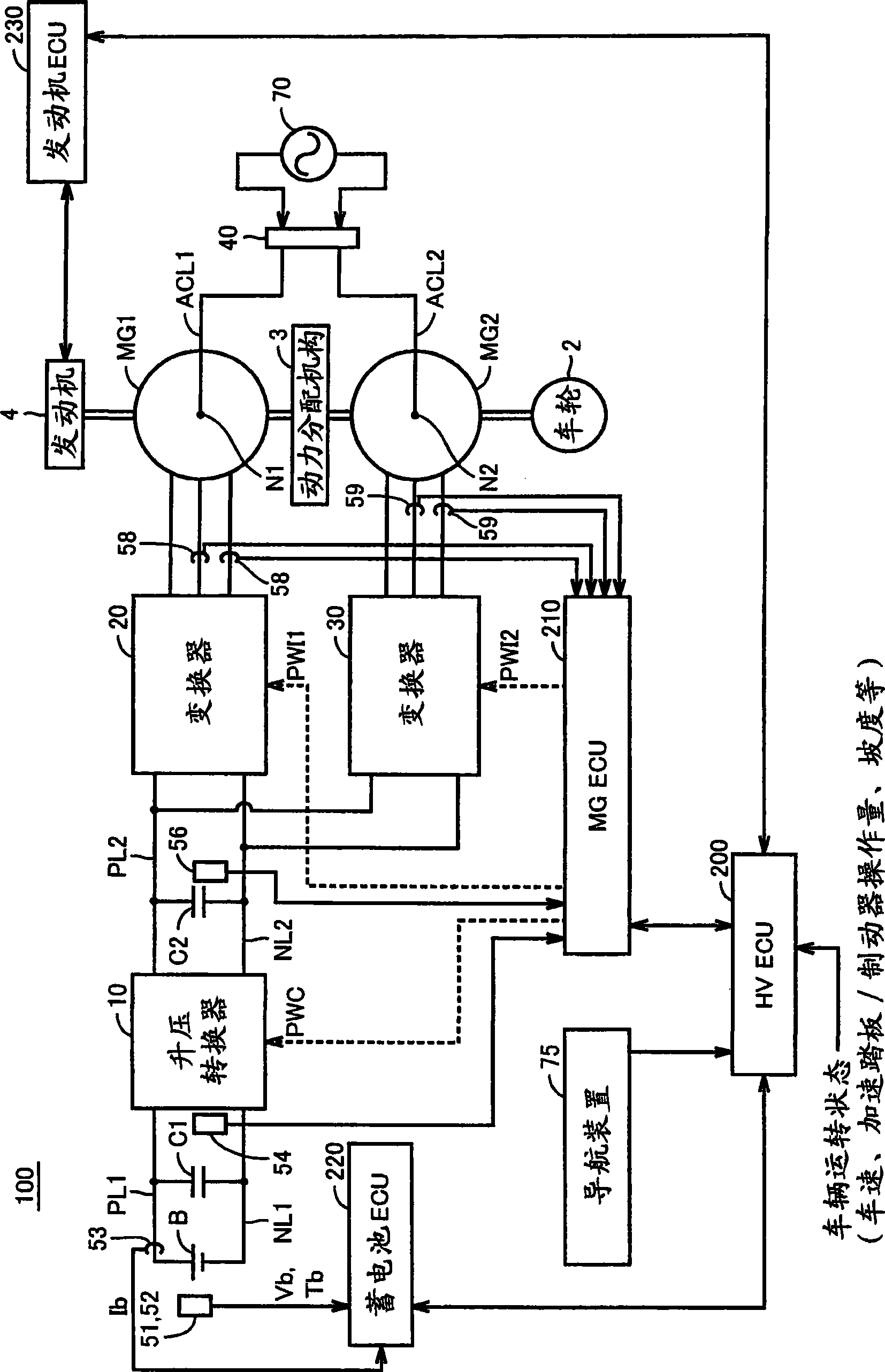
[0054] figure 1 It is a block diagram illustrating an overall schematic configuration of a hybrid vehicle according to an embodiment of the present invention.

[0055] refer to figure 1 , the hybrid vehicle 100 includes wheels 2, a power distribution mechanism 3, an engine 4, and motor generators MG1, MG2. Furthermore, hybrid vehicle 100 further includes power storage device B, boost converter (converter) 10, inverters (inverters) 20, 30, connector 40, navigation device 75, capacitors C1 and C2, positive pole lines PL1, PL2, and negative pole lines NL1, NL2.

[0056] Furthermore, as an electronic control unit (ECU) of vehicle-mounted equipment, hybrid vehicle 100 includes HVECU 200 that controls the entire hybrid system; battery ECU 220 for managing and controlling the charging and discharging state of power storage device B; and engine ECU 230 for controlling the operating state of engine 4 . Each ECU is connected in such a way that data / information can be exchanged with ...

Embodiment approach 2

[0118] In the following embodiments, modifications of the travel control of hybrid vehicle 100 described in Embodiment 1 will be described. Therefore, in each of the following embodiments, the configuration of the hybrid vehicle 100 and the management of the remaining capacity of the power storage device before arriving at a predetermined point (home) are the same as those in the first embodiment.

[0119] Figure 9It is a schematic block diagram illustrating travel control of the hybrid vehicle according to the second embodiment.

[0120] refer to Figure 9 , in Embodiment 2, output distribution determination unit 500 includes EV travelable distance prediction unit 502 and full charge detection unit 504 .

[0121] EV-runable distance prediction unit 502 predicts a travelable distance (EV-runable distance) using only the output of motor generator MG2 based on the current battery SOC. Preliminary creation of a one-dimensional map (map) with the battery SOC as an argument and...

Embodiment approach 3

[0135] In Embodiment 3, driving control reflecting the progress of deterioration of battery B (power storage device) will be described.

[0136] Figure 12 It is a schematic block diagram illustrating travel control of the hybrid vehicle according to Embodiment 3 of the present invention.

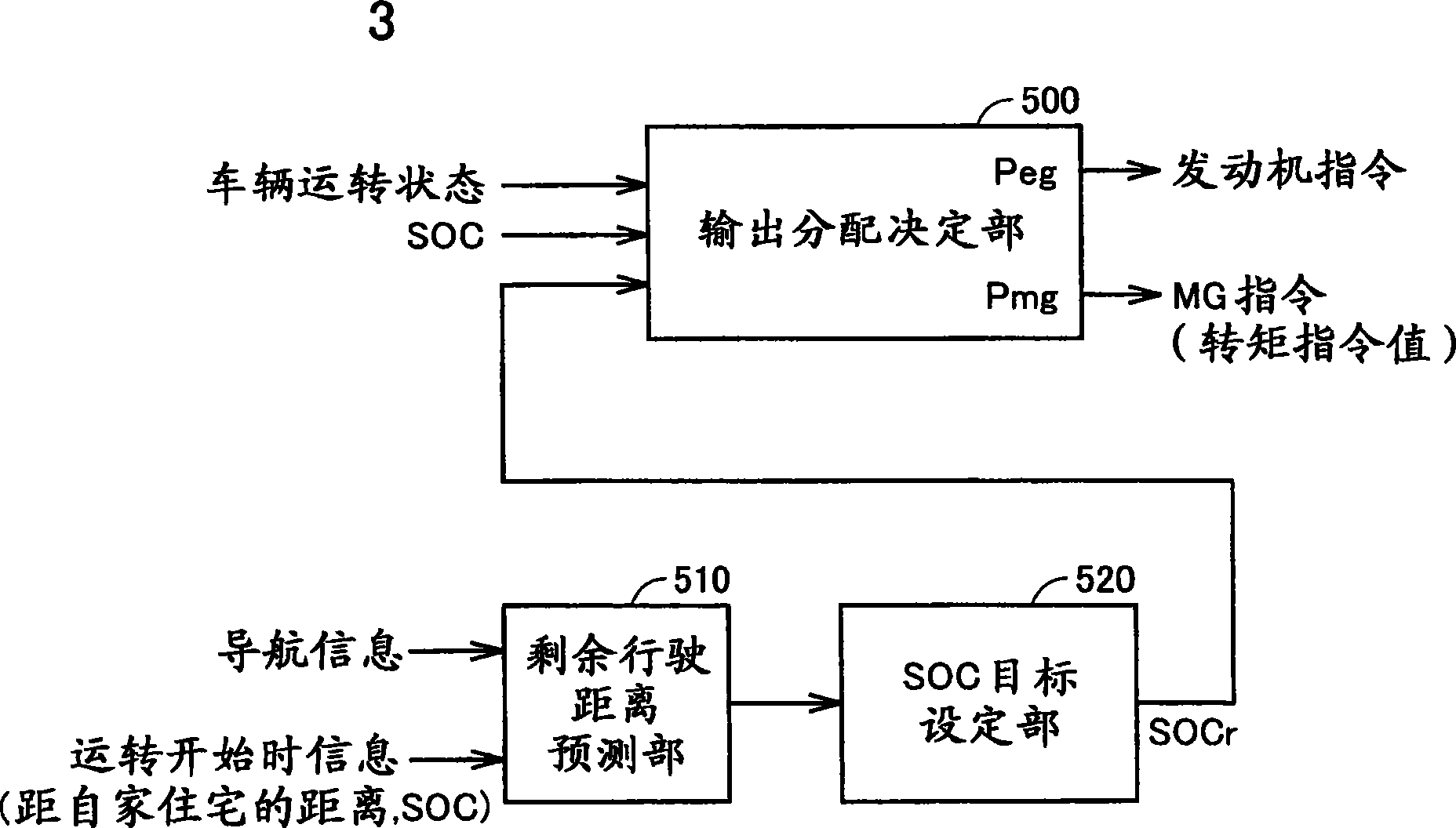
[0137] right Figure 12 and image 3 By comparison, it can be seen that the degradation determination unit 600 is further provided in the traveling control of the hybrid vehicle according to the third embodiment. Deterioration determination unit 600 obtains the degree of deterioration of battery (power storage device) B based on temperature Tb, current Ib, voltage Vb, etc. of battery B.

[0138] For example, by setting a diagnosis mode in which a constant current is output in a pulse form from battery B after the operation of the hybrid vehicle ends, it is possible to estimate Deterioration degree of battery B. For example, by periodically executing such a diagnosis mode every time a c...


PUM


Abstract

An SOC target (SOCr) is a control target of a remaining capacity (SOC) of an accumulation device (battery) having a characteristic that the internal loss increases in a low SOC region. The SOC target is set to a first value (S0) corresponding to a remaining capacity target upon reaching a predetermined point when the remaining travel distance up to a predetermined point where the accumulation device can be charged from outside has become shorter than a predetermined distance (Dr). Thus, the hybrid vehicle can perform EV travel by power consumption of the accumulation device.On the other hand, when the remaining travel distance is not smaller than the predetermined distance Dr, the SOC target (SOCr) is set to a second value (S1) in the SOC region where the loss of the accumulation device is smaller than the first value (S0). Thus, it is possible to reduce the power consumption in the hybrid vehicle which performs such a remaining capacity management that the remaining capacity of the accumulation device upon arrival at a predetermined point is a predetermined value.

Description

technical field [0001] The invention relates to a hybrid electric vehicle and a running control method of the hybrid electric vehicle. More specifically, it relates to a hybrid vehicle including an internal combustion engine and an electric motor configured to generate vehicle running power as power sources, and a travel control method for the hybrid vehicle. Background technique [0002] In recent years, hybrid vehicles have attracted attention as vehicles that take care of the environment. A hybrid vehicle is a vehicle in which driving power is generated by an electric motor in addition to the conventional engine. That is, the hybrid vehicle seeks to reduce fuel consumption by appropriately performing engine-only travel, motor-only travel, and motor-and-engine travel in a running state. Typically, for example, travel control is performed such that in an operating region where the engine efficiency deteriorates, such as when the vehicle starts running at a low speed, a mo...

Claims


Application Information

Patent Timeline
Patent Type & Authority Applications(China)
IPC IPC(8): B60W10/26B60W10/08B60K6/445B60W20/00B60L11/14G01C21/00B60W10/06B60L50/16G01C21/26
CPCY02T10/6286Y02T10/6217Y02T10/7022Y02T10/7044B60L2260/54B60L11/1812B60W10/06Y02T90/14B60W2510/244B60K6/445Y02T10/7291Y02T10/7005Y02T90/16B60W2710/244B60L11/005B60L15/007B60W2540/04Y02T10/84Y02T10/705B60L11/123B60L11/1861B60L2220/54B60L11/1814B60W10/08B60L11/187Y02T10/6239B60W2510/246B60L2260/52Y02T90/161Y02T10/641Y02T90/127Y02T90/162B60W2550/402B60W20/00B60L2260/56Y02T10/6269B60L11/14Y02T10/7077B60W10/26G01C21/26Y02T10/7088B60L2240/62B60L2220/14Y02T10/7072B60L53/22B60L50/40B60L50/61B60L50/16B60L53/24B60L58/12B60L58/24B60W2540/215B60W2556/50Y02T10/62Y02T10/64Y02T10/70Y02T10/72B60W50/082B60W50/085B60W20/12Y02T90/12
Inventor 相马贵也洪远龄丹羽俊明
Owner TOYOTA JIDOSHA KK
Why Eureka
Try Eureka