
Ferrule, method of manufacturing optical waveguide connector using the ferrule, and optical waveguide connector

A technology for optical waveguide and connectors, applied in the field of optical waveguide connectors, can solve the problems that the productivity of optical waveguide connectors cannot be improved, and achieve the effects of preventing axial deviation and suppressing connection loss

Inactive Publication Date: 2009-09-02
SUMITOMO ELECTRIC IND LTD +1
View PDF2 Cites 14 Cited by
  • Summary
  • Abstract
  • Description
  • Claims
  • Application Information

AI Technical Summary

Problems solved by technology

[0016] For the optical waveguide connector 6 using the ferrule 7 divided into two halves as described above, an assembly step of bonding and combining the upper body 7a and the lower body 7b during the manufacturing process is required, so that due to assembling the The problem that the productivity of the optical waveguide connector cannot be improved due to the steps of the ferrule 7

Method used


Image

  • Ferrule, method of manufacturing optical waveguide connector using the ferrule, and optical waveguide connector
  • Ferrule, method of manufacturing optical waveguide connector using the ferrule, and optical waveguide connector
  • Ferrule, method of manufacturing optical waveguide connector using the ferrule, and optical waveguide connector

Examples


Embodiment Construction

[0053] Hereinafter, a ferrule of the present invention, a method of manufacturing an optical waveguide connector using the same, and preferred embodiments of the optical waveguide connector will be described in detail with reference to the accompanying drawings.

[0054] The term "optical waveguide" in this specification includes flat plate-type optical transmission devices having various rectangular cross-sections, such as optical waveguides, polymer waveguides, and optical fiber ribbons. In this embodiment, a case where a polymer waveguide is applied to an optical transmission path is described.

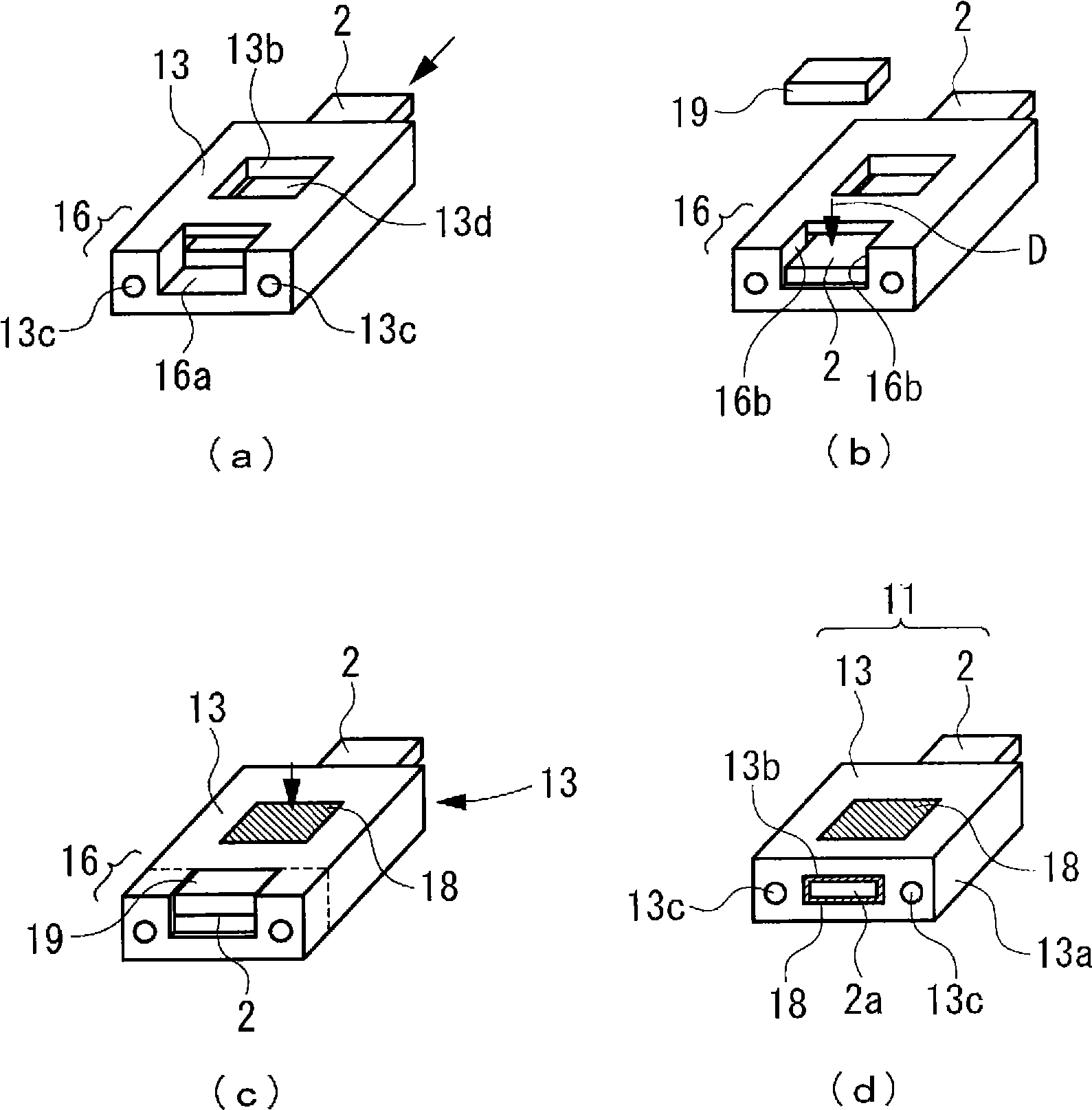
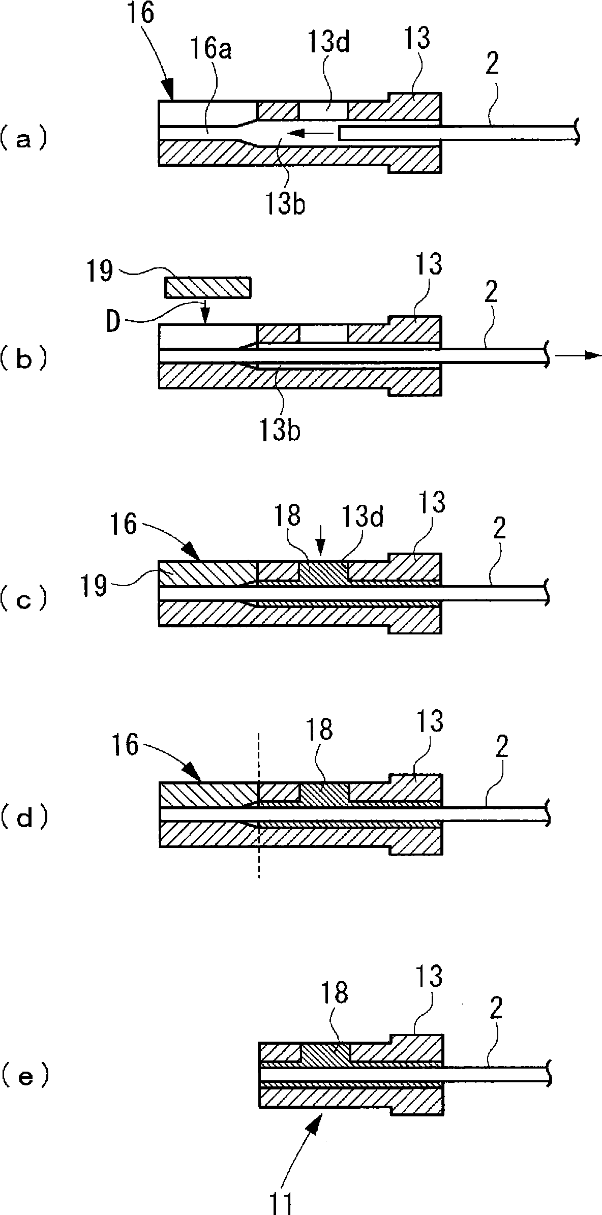
[0055] figure 1 is a perspective view showing a ferrule of the present invention and a first embodiment of a method of manufacturing an optical waveguide connector according to the present invention using the ferrule. In the drawings, (a) shows the state where the optical waveguide is passed through the insertion hole of the ferrule, (b) shows the state where the optical waveguid...


PUM


Abstract

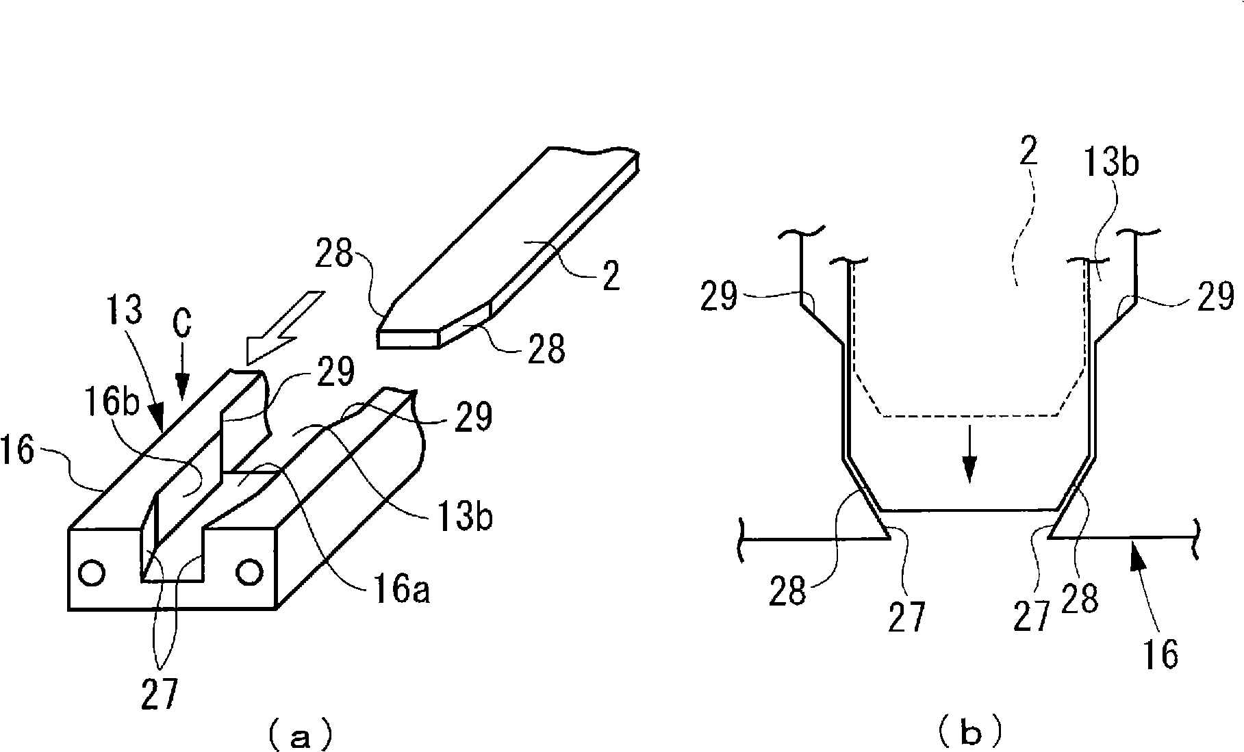
Provided is an optical waveguide connector manufacturing method capable of improving the productivity of a ferrule member and suppressing the connection loss of a partner connector. An optical waveguiProvided is an optical waveguide connector manufacturing method capable of improving the productivity of a ferrule member and suppressing the connection loss of a partner connector. An optical waveguide connector (11) is obtained by executing a centering step of position-regulating the leading end of an optical waveguide (2) inserted into the insert hole (13b) of a ferrule member (13), with the pode connector (11) is obtained by executing a centering step of position-regulating the leading end of an optical waveguide (2) inserted into the insert hole (13b) of a ferrule member (13), with the positioning portion of a positioning member (16) arranged to confront the leading end of the ferrule member (13), thereby to center the optical waveguide with respect to the ferrule member (13), an adhesitioning portion of a positioning member (16) arranged to confront the leading end of the ferrule member (13), thereby to center the optical waveguide with respect to the ferrule member (13), an adhering step of filling an adhesive (18) into the clearance between the optical waveguide (2) inserted into the insert hole (13b) and the insert hole (13b), thereby to fix the optical waveguide (2) in thring step of filling an adhesive (18) into the clearance between the optical waveguide (2) inserted into the insert hole (13b) and the insert hole (13b), thereby to fix the optical waveguide (2) in the ferrule member (13), and a cutting step of cutting off the leading end of the ferrule member (13) including the positioning member (16).e ferrule member (13), and a cutting step of cutting off the leading end of the ferrule member (13) including the positioning member (16).

Description

technical field [0001] The present invention relates to a ferrule for accommodating an optical waveguide for connector connection of the optical waveguide with another optical component, a method of manufacturing an optical waveguide connector using the ferrule, and an optical waveguide connector using the ferrule. Background technique [0002] A known Figure 4 The configuration shown is for an optical waveguide connector for connector-connecting an optical waveguide, such as a fiber optic ribbon or a polymer waveguide, with another optical component. [0003] In an optical waveguide 1 as shown in the figure, a front end portion of a planar optical waveguide 2 is housed and held in a ferrule 3 . [0004] Such as Figure 4 As shown in (a), in the ferrule 3, the insertion hole 3b through which the optical waveguide 2 will pass is formed penetratingly in the main body 3a which has a substantially rectangular parallelepiped shape. A pair of positioning holes 3c into which a po...

Claims


Application Information

Patent Timeline
Patent Type & Authority Applications(China)
IPC IPC(8): G02B6/36G02B6/13
CPCG02B6/3846G02B6/3855
Inventor 大村真树田村充章古宇田光中野嘉一郎小野秀之田中千惠美
Owner SUMITOMO ELECTRIC IND LTD
Learn More