A switched light element array and method of operation

一种发光元件、阵列的技术,应用在发光元件的半导体器件、电气元件、电致发光光源等方向,能够解决增加LED阵列功耗启动和停用时间、增加成本、降低LED性能等问题

Inactive Publication Date: 2009-09-02
KONINK PHILIPS ELECTRONICS NV
View PDF1 Cites 3 Cited by
  • Summary
  • Abstract
  • Description
  • Claims
  • Application Information

AI Technical Summary

Problems solved by technology

[0005] The high number of components used to operate and control the LED array degrades LED performance in several ways, each component increases the power consumption of the LED array and causes parasitic effects that contribute to reducing the turn-on and turn-off times of the LEDs
Additionally, when LED arrays are implemented in high temperature applications, individual components will require high temperature ratings, and this performance will further increase the cost of each required component

Method used


Image

  • A switched light element array and method of operation
  • A switched light element array and method of operation
  • A switched light element array and method of operation

Examples


Embodiment Construction

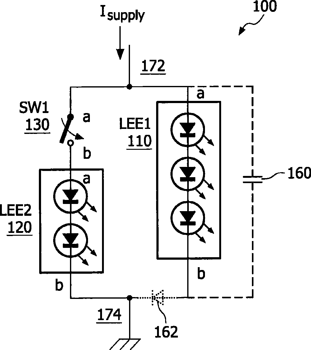
[0030] figure 1 An exemplary embodiment of a light emitting element array 100 according to the present invention is shown. The array 100 includes a first light emitting element (LEE) 110 having a first terminal 110a and a second terminal 110b, a second LEE 120 having a first terminal 120a and a second terminal 120b connected to the second terminal 110b of the first LEE 110 , and a switch 130 having a first terminal 130a connected to the first terminal 110a of the first LEE 110 and a second terminal 130b connected to the first terminal 120a of the second LEE 120 . As used herein, the term "light emitting element" or "LEE" refers to any light emitting element, circuit, device or component, such as a light emitting diode (LED), organic light emitting diode (OLED), AC LED, laser diode, or any other lighting element, Such as incandescent lamps and so on.

[0031] The first terminal of the switch 130 and the first terminal of the first LEE 110 are commonly connected to a first pow...


PUM


Abstract

A switched light element array includes first, second and third light emitting elements, and first and second switches. The first light emitting element includes first and second terminals, and the second light emitting element includes a first terminal, and a second terminal coupled to the second terminal of the first light emitting element. The third light emitting element includes a first terminal coupled to the first terminal of the first light emitting element and a second terminal. The first switch includes a first terminal coupled to each of the first terminals of the first and third light emitting elements and a second terminal coupled to the first terminal of the second light emitting element. The second switch includes a first terminal coupled to the second terminal of the third light emitting element, and a second terminal coupled to each of the second terminals of the first and second light emitting elements.

Description

technical field [0001] The present invention relates generally to devices using light emitting elements, and more particularly to arrays of light emitting elements, devices and methods of operation thereof. Background technique [0002] Light emitting elements such as light emitting diodes (LEDs) are increasingly used in a variety of applications, some examples being backlights in liquid crystal displays, flashes for charge-coupled device cameras, general lighting, and others. In many of these applications, LEDs of different colors are used, for example arranged in an array to create various color points. The operating conditions of an LED array can be as varied as the application of the array, such operating conditions requiring, for example, low power, high operating temperature, and fast LED activation and deactivation times. [0003] Typically, each LED array is powered by a driver circuit that can operate in one of a number of different drive modes depending on the des...

Claims


Application Information

Patent Timeline
Patent Type & Authority Applications(China)
IPC IPC(8): H05B33/08H05B44/00
CPCH05B33/0818Y02B20/346H05B33/0857H05B45/37Y02B20/30H05B45/10F21Y2105/10F21Y2115/15F21Y2115/10
Inventor H·J·G·拉德马彻V·舒尔茨
Owner KONINK PHILIPS ELECTRONICS NV
Why Eureka
Try Eureka