Supercharge Your Innovation With Domain-Expert AI Agents!

Mould locking air pressure swelling mechanism for rotary bottle blowing machine

A technology of tensioning mechanism and mold air pressure, which is applied in the field of mold clamping air pressure tensioning mechanism of rotary blow molding machine, can solve the problems of increased production cost, mold expansion, and large energy consumption, so as to achieve less wear of parts, ensure the pass rate, The effect of low energy consumption

Inactive Publication Date: 2009-09-09
汪祥建
View PDF5 Cites 8 Cited by
  • Summary
  • Abstract
  • Description
  • Claims
  • Application Information

AI Technical Summary

Problems solved by technology

The mold clamping mechanism of the existing bottle blowing machine has the disadvantages of large volume and large space occupation, and is not suitable for use on a rotary blow molding machine. Therefore, the applicant has applied for Chinese patent ZL200520015537.1. The mold clamping mechanism is located at one end of the template A clamping ring is formed, and a clamping hole is formed in the clamping ring. A lifting rod is installed in the clamping ring. The lifting rod drives the clamping pin through the cross bar. The clamping pin matches the clamping hole of the clamping ring. The advantage is that it is small in size, takes up less space, and is suitable for rotary blow molding machines
However, the disadvantage of this clamping mechanism is that the mold opening and clamping force required during mold clamping and demoulding is very large, which may easily cause parts to wear out, and mold gaps will be generated after parts are worn out, which will easily cause mold expansion, reduce the pass rate of bottles, and open the mold. , The large clamping force consumes a lot of energy, which increases the production cost

Method used


Image

  • Mould locking air pressure swelling mechanism for rotary bottle blowing machine
  • Mould locking air pressure swelling mechanism for rotary bottle blowing machine

Examples


Embodiment Construction

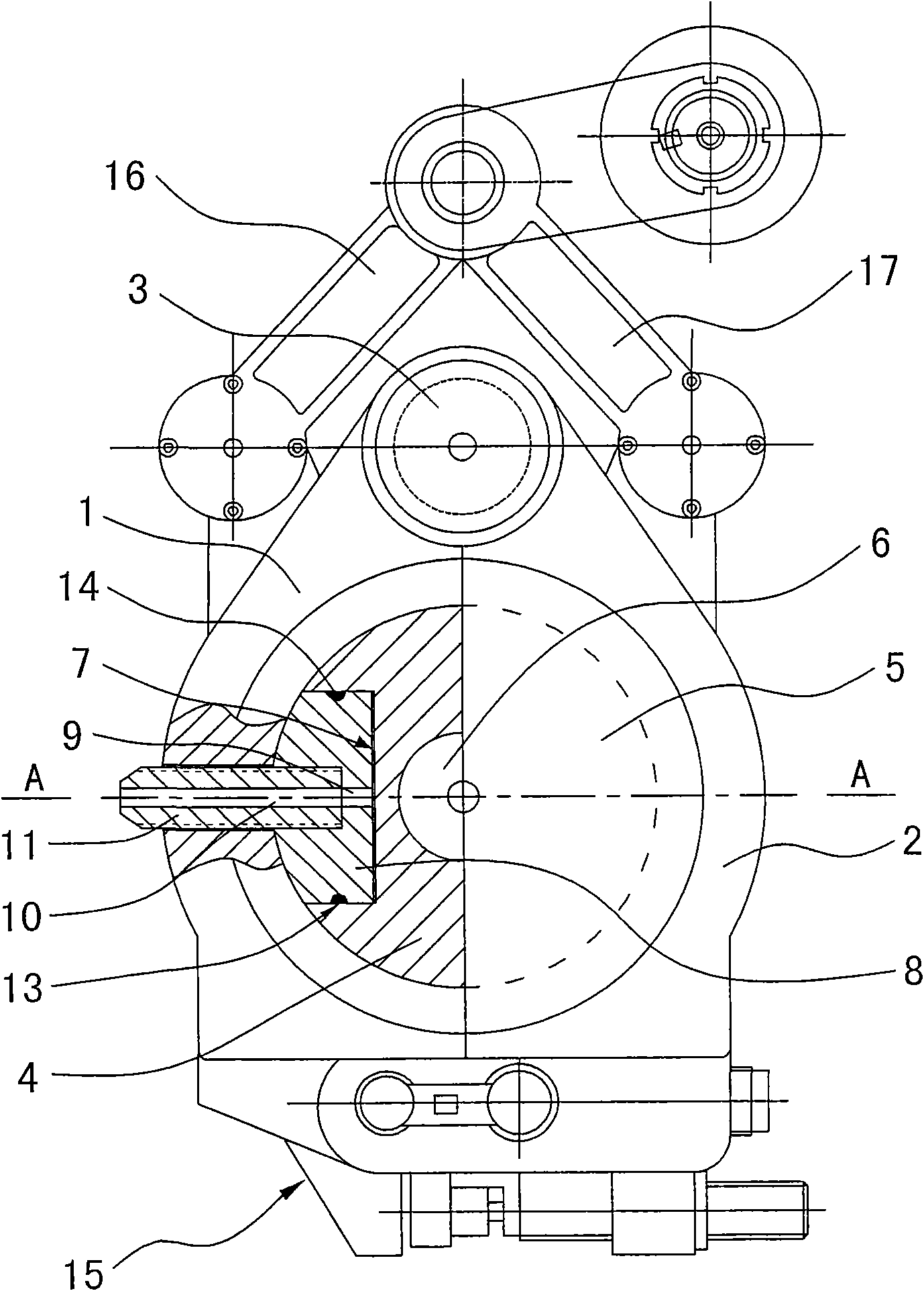
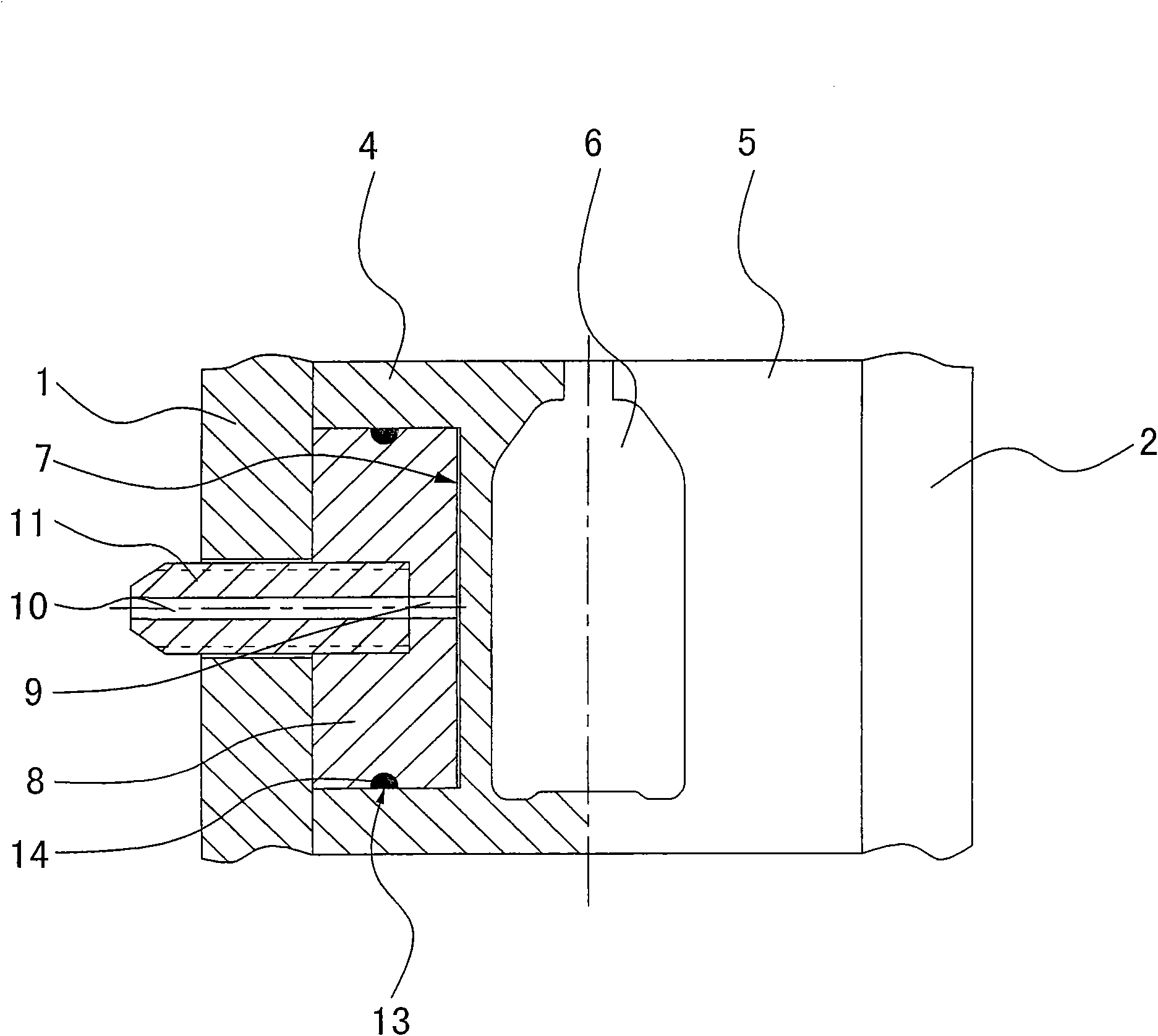
[0009] The invention relates to a clamping air pressure tensioning mechanism of a rotary blow molding machine, such as figure 1 , figure 2 As shown, it comprises a rotating frame, and left and right templates 1, 2 are installed in the frame, and one end of the left and right templates is connected to each other by a main shaft 3, and a mold locking mechanism 15 is installed at the other end of the left and right templates, and the main shaft Fixed in the frame, respectively install molds 4 and 5 in the left and right templates, mold cavities 6 are formed in the molds, the left and right templates are connected with connecting rods 16 and 17 and driven by the opening and closing mechanism, which is characterized in that the mold Open the die (groove) 7 at the back (the area of ​​the groove is the maximum range allowed by the mould), the convex module 8 is installed in the concave mold 7, and the concave ring 13 is formed around the convex module 8, and O is installed in the co...


PUM


Abstract

The invention relates to a mould locking air pressure swelling mechanism for a rotary bottle blowing machine, which comprises a rotary machine frame, wherein the machine frame is provided with a left template and a right template inside; one end of the left template is mutually connected with one end of the right template by a main shaft; the other end of the left template and the other end of the right template are provided with mould locking mechanisms; the main shaft is fixed in the machine frame; the left template and the right template are provided with a mould inside respectively; the mould is provided with a mould cavity; and the left template and the right template are driven by a mould opening and closing mechanism. The mechanism is characterized in that the back of the mould is provided with a concave mould; the concave mould is provided with a convex module; the periphery of the convex module is provided with a concave ring; the concave ring is provided with an O-shaped ring inside; the convex module is provided with a vent hole inside; the convex module is provided with a blowing joint; the blowing joint is provided with a blowing hole inside; the blowing hole corresponds to the vent hole; and the blowing joint passes though the templates.

Description

technical field [0001] The invention relates to a mold clamping air pressure tensioning mechanism of a rotary bottle blowing machine, which belongs to the field of plastic machinery. Background technique [0002] When processing plastic hollow containers, the process of injection and stretch blowing can be used, that is, firstly, the plastic raw materials are injected into preforms, and then the preforms are heated, and then the heated plastic preforms are sent to the blow molding machine for stretch blow molding. . There are many types of existing plastic blow molding machines, which can be divided into translational opening and closing templates and clamp-type opening and closing templates according to the structure of the template and the different opening and closing methods. The clamp-type opening and closing formwork relies on the connecting rod to drive the left and right two formworks to rotate and open, so one of the two forms is connected to each other, and the ot...

Claims


Application Information

Patent Timeline
Patent Type & Authority Applications(China)
IPC IPC(8): B29C49/56B29L22/00
Inventor 汪祥建
Owner 汪祥建
Features
  • R&D
  • Intellectual Property
  • Life Sciences
  • Materials
  • Tech Scout
  • Unparalleled Data Quality
  • Higher Quality Content
  • 60% Fewer Hallucinations
Learn More