Production line for light guide plates

A technology of light guide plate and production line, applied in the direction of light guide, optics, optical components, etc., can solve the problems of lengthy, unable to increase production, cumbersome process, etc., to achieve the effect of simple process, enhance industrial competitiveness, and increase output

Inactive Publication Date: 2009-09-09
洪文修
View PDF0 Cites 27 Cited by
  • Summary
  • Abstract
  • Description
  • Claims
  • Application Information

AI Technical Summary

Problems solved by technology

[0007] The purpose of the present invention is to provide a production line for light guide plates to overcome the defects that the existing l

Method used


Image

  • Production line for light guide plates
  • Production line for light guide plates
  • Production line for light guide plates

Examples


Embodiment Construction

[0030] In order to have a further understanding and understanding of the purpose, characteristics and effects of the present invention, please cooperate with the [simplified description of the drawings] to describe in detail as follows:

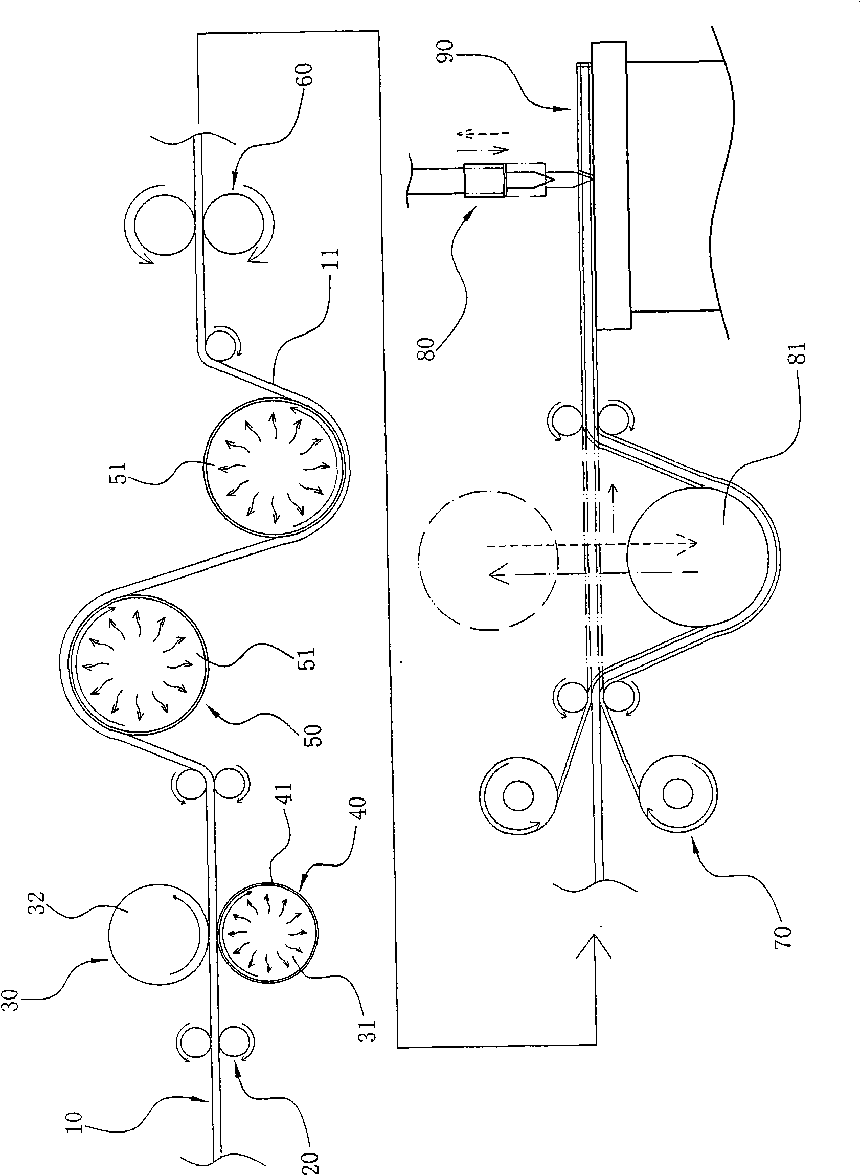
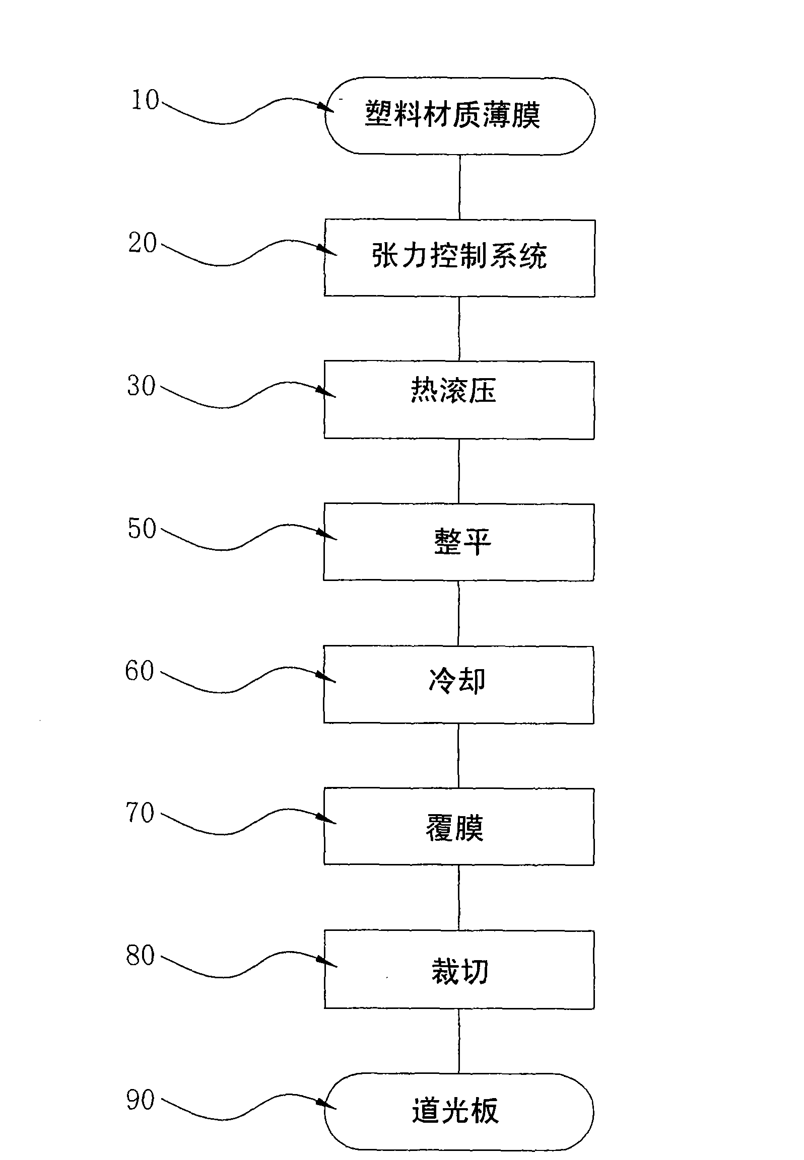
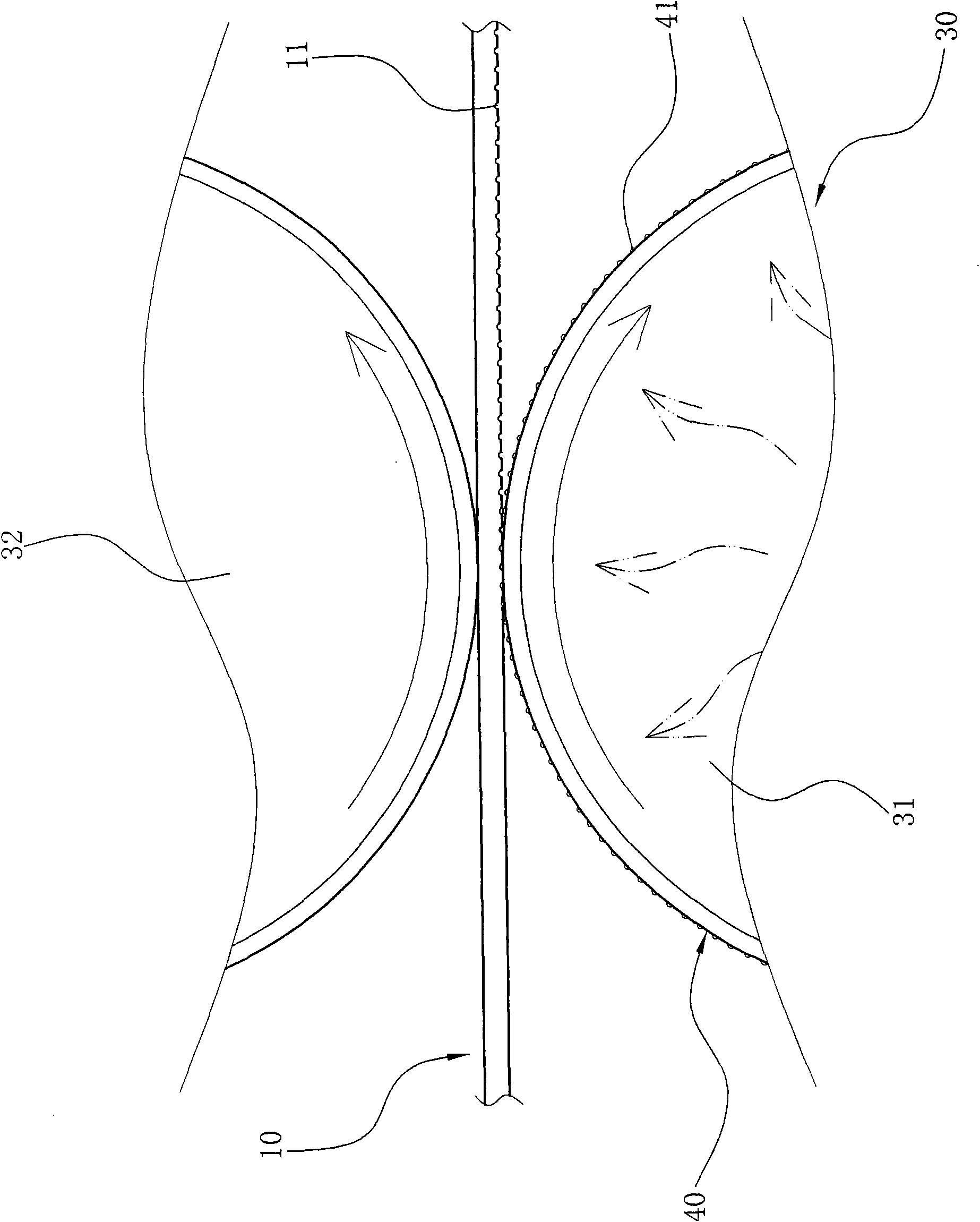
[0031] Usually according to the present invention, first by figure 1 match figure 2 As shown, the plastic material film (LightGuide Film) 10 is conveyed by the tension control system 20, and can run forward. During the running process, it passes through hot rolling 30, metal film 40, leveling 50, Cooling 60, coating 70, cutting 80 and other processes can complete the forming of the light guide plate 90; wherein,

[0032] The tension control system 20 is the conveying wheel, which is mainly used to drive the plastic material film 10 forward, so as to continue the processes of hot rolling 30, leveling 50, cooling 60, coating 70, cutting 80 into a consistent process flow line, and can be used to drive the output of the formed light guide plat...


PUM


Abstract

The invention relates to a production line for light guide plates. Plastic films of the light guide plates run forwards through the transportation of a tension control system, and are subjected to processing procedures such as hot rolling with metal films, leveling-up, cooling, film coating, cutting and the like in turn in the running process to complete the forming of the light guide plates.

Description

technical field [0001] The invention relates to a production line of a light guide plate, in particular to a production line of a light guide plate in which microporous grooves are hot-rolled on a plastic material film, so that the output per unit time can be greatly increased. Background technique [0002] Since LCD is not a self-illuminating display device, it needs to use an external light source to achieve the display effect. For example, the backlight module (Backlight Module) is a technology widely used in LCD, and the light guide plate is an important component of the backlight module. , which is mainly used to guide the transmission direction of the emitted light beam, so as to convert the line light source or point light source into a surface light source and then emit it. [0003] At present, the production method of the existing thin light guide plate is mainly to use the injection molding machine to melt the plastic into a nearly liquid state, and then inject it ...

Claims


Application Information

Patent Timeline
IPC IPC(8): G02B6/00B29C59/04B29C53/18
Inventor 洪文修
Owner 洪文修
Why Eureka
Try Eureka