Eureka AIR delivers breakthrough ideas for toughest innovation challenges, trusted by R&D personnel around the world.

Method for repairing mask plate

A repair method and reticle technology, applied in the field of reticle repair, can solve the problem of not being able to find a reproducible graphic, and achieve the effect of low process cost

Inactive Publication Date: 2009-09-09
SEMICON MFG INT (SHANGHAI) CORP
View PDF1 Cites 2 Cited by
  • Summary
  • Abstract
  • Description
  • Claims
  • Application Information

AI Technical Summary

Problems solved by technology

[0006] The method of repairing the reticle by the focused ion beam machine requires a reproducible mask pattern on the surface of the reticle to be repaired. However, in actual production, it may not be possible to find a reproducible pattern that meets the requirements to repair the defective pattern. Therefore There is a need for a method of repairing a reticle to be repaired without a reproducible mask pattern on the surface of the reticle to be repaired

Method used


Image

  • Method for repairing mask plate
  • Method for repairing mask plate
  • Method for repairing mask plate

Examples


Embodiment Construction

[0023] The specific embodiments of the reticle repair method of the present invention will be described in detail below with reference to the accompanying drawings.

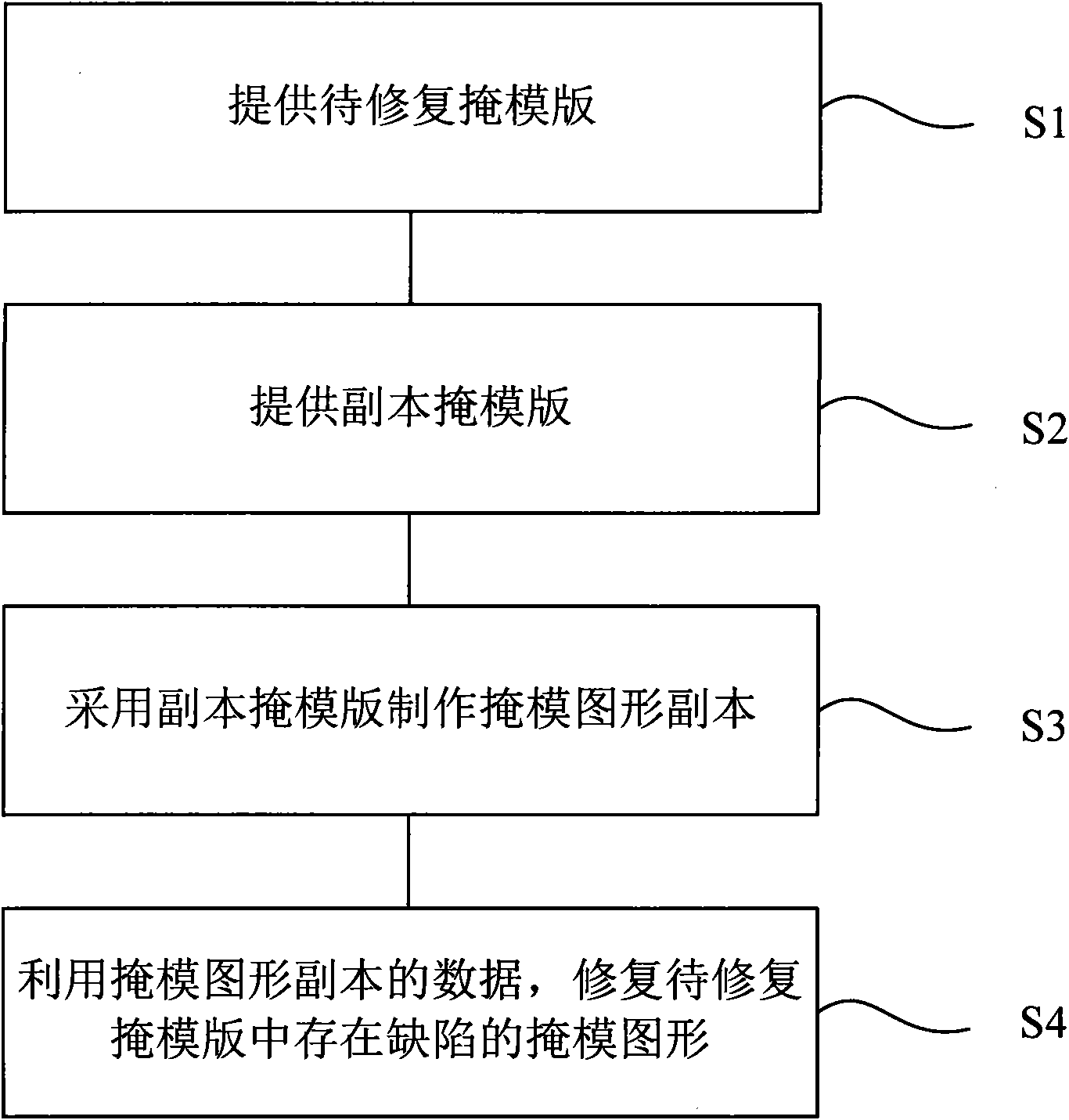
[0024] as attached figure 1 Shown is the flow chart of the implementation steps of the specific embodiment of the reticle repair method. Including the following steps: step S1, providing a reticle to be repaired; step S2, providing a duplicate reticle; step S3, using the duplicate reticle to make a mask pattern replica; step S4, using the data of the mask pattern replica to repair the to-be-repaired reticle There are defects in the mask pattern.

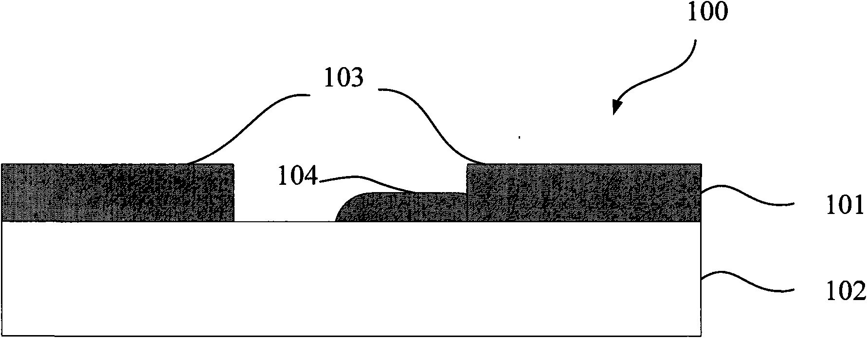
[0025] as attached figure 2 As shown, referring to step S1, a reticle 100 to be repaired is provided. The reticle 100 to be repaired includes a light shielding layer 101 and a substrate 102 . A mask pattern 103 is formed on the light shielding layer, and defects 104 exist in the mask pattern 103 .

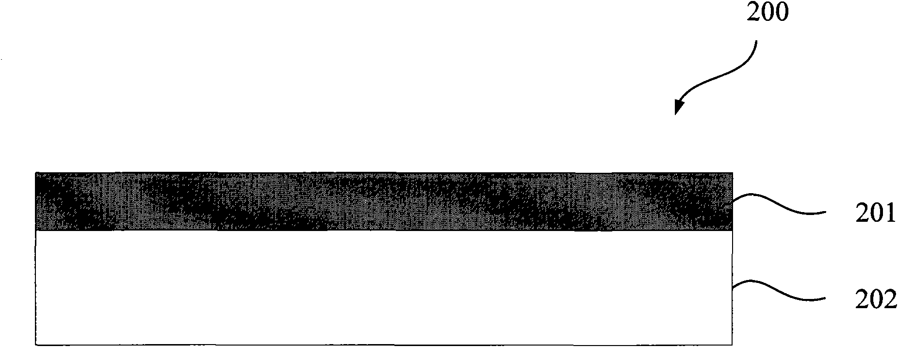
[0026] as attached image 3 As shown, referring to step S2, a re...


PUM

PropertyMeasurementUnit
widthaaaaaaaaaa

Abstract

The invention relates to a method for repairing a mask plate, which comprises the following steps: providing the mask plate to be repaired comprising a mask pattern with defects; providing a copied mask plate comprising an un-etched light shield layer of which the area is larger than that of the mask pattern with the defects in the mask plate to be repaired; making a mask pattern copy with the copied mask plate; and repairing the mask pattern with the defects in the mask plate to be repaired by making use of data of the mask pattern copy. The method has the advantage of solving the technical problem of repairing the mask plate under that condition that no replicable patterns are positioned on the surface of the mask plate to be repaired.

Description

【Technical field】 [0001] The invention relates to the field of integrated circuit manufacturing, in particular to a method for repairing a mask. 【Background technique】 [0002] Reticles are one of the key components in the field of integrated circuit manufacturing. A common mask includes a transparent substrate and a light shielding layer on the surface of the substrate. The light shielding layer is usually made of a metal-containing material, such as chromium or molybdenum silicide. The pattern required in each step of the integrated circuit plane process is fabricated in the light shielding layer, and the pattern in the light shielding layer is transferred to the surface of the semiconductor substrate by photolithography, and a specific pattern is formed on the surface of the semiconductor substrate. [0003] The common reticle manufacturing method is to provide an initial reticle, coat a layer of photoresist on the surface of the light-shielding layer of the initial reti...

Claims


Application Information

Patent Timeline
Patent Type & Authority Applications(China)
IPC IPC(8): G03F1/00G03F1/72
Inventor 钱芳
Owner SEMICON MFG INT (SHANGHAI) CORP
Why Eureka
Eureka Blog
Learn More