Burr-free clock switching circuit

A technology of clock switching and switching circuits, applied in logic circuits using specific components, logic circuits using basic logic circuit components, generating/distributing signals, etc., can solve problems such as inability to change and circuits that cannot be switched

Inactive Publication Date: 2009-09-09
袁园
View PDF3 Cites 29 Cited by
  • Summary
  • Abstract
  • Description
  • Claims
  • Application Information

AI Technical Summary

Problems solved by technology

[0011] The schematic diagram of this method is figure 2 As shown, this circuit has this problem: if the rising edge of clk2 is after the falling edge of clk1 and before the rising edge of clk1, then the output clock will have a low-level glitch between the falling edge of clk1 and the rising edge of clk2, such as image 3 shown
[0013] The schematic diagram of this method is Figure 4 As shown, this circuit has this problem: if switch_0=1, after switching to clk_0, clk_0 fails and does not change anymore. At this time, even if switch_0=0, since the s0_sync signal cannot be changed, the output of clk_1_latch remains 0, and the circuit cannot be switched to clk_1, such as Figure 5 shown

Method used


Image

  • Burr-free clock switching circuit
  • Burr-free clock switching circuit
  • Burr-free clock switching circuit

Examples


Embodiment Construction

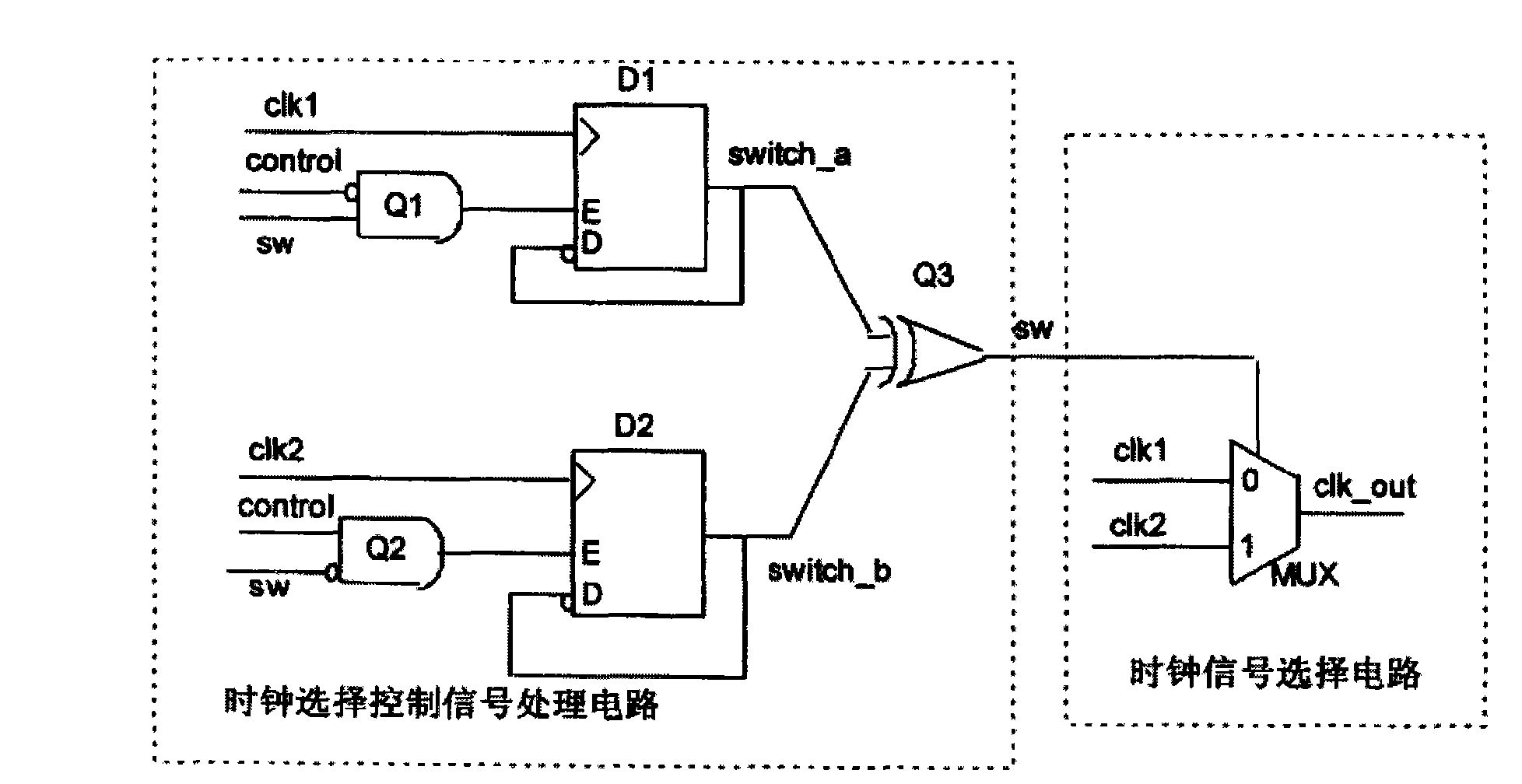
[0044] The glitch-free clock switching circuit of the present invention includes two clock detection modules and a clock switching module, the two clock detection modules are respectively used to detect whether the two clock signals to be switched are faulty, and the clock switching module is used to detect the clock according to the clock detection results of the two clock detection modules The switching signal and the clock output enable signal are selected to ensure that the circuit outputs the correct switching clock signal when switching occurs.

[0045] The clock detection module and the clock switching module will be described in detail below with reference to the accompanying drawings.

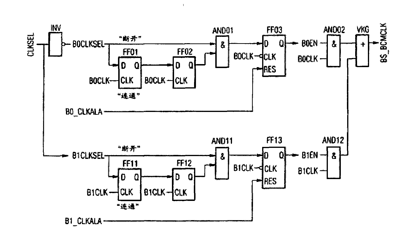
[0046] The clock detection module can detect the state of the clock to be switched in real time, and sensitively detect whether the clock to be switched jumps, that is, it can be detected quickly after the clock fails, such as Figure 7 As shown, the clock detection module is implemented...


PUM


Abstract

The invention provides a burr-free clock switching circuit. The burr-free clock switching circuit comprises a single-level switching circuit or multilevel switching circuits so as to realize the switching of two or a plurality of clock signals. The switching circuit at each level comprises a first clock detection module, a second clock detection module and a clock switching module; wherein the first and second clock detection modules are used for detecting whether the two clock signals to be switched have failures respectively; and the clock switching module is used for selecting a switching signal and a clock output enabling signal according to clock detection results of the two clock detection modules. The clock detection modules are used to detect whether the clock signals to be switched jump normally; and the switching circuit is controlled according to the detection results so as to ensure that a required clock is reliably switched to even if errors happen to the clock to be switched.

Description

technical field [0001] The invention relates to the field where a system contains a plurality of clock domains with different frequencies, and part or all of the system needs to be switched by clock selection, especially a glitch-free clock switching circuit. Background technique [0002] With the increasing integration of large-scale programmable logic devices, more and more functions are implemented in the same logic device, so it is necessary to process more than two clock domain signals with different rates and phases in the same logic device. requirements, which requires logic devices to support switching between different clocks. At this time, the quality of the clock switching circuit greatly affects the performance and stability of the entire system. [0003] The current clock switching is as follows: [0004] 1. Directly use the logic selector to select the switch [0005] This method is the simplest, but the effect is also the worst. Without any burr removal met...

Claims


Application Information

Patent Timeline
Patent Type & Authority Applications(China)
IPC IPC(8): G06F1/04H03K19/173
Inventor 张庆闫晓艳姜铁君
Owner 袁园
Why Eureka
Try Eureka