Cable protective sleeve and lead clamp thereof

A technology for protective sleeves and cables, applied in electrical components and other directions, can solve the problems of accelerated cable aging, increased safety hazards, and complicated operations, and achieves the effect of reducing friction and increasing flexibility

Inactive Publication Date: 2009-09-09
许福章
View PDF0 Cites 4 Cited by
  • Summary
  • Abstract
  • Description
  • Claims
  • Application Information

AI Technical Summary

Problems solved by technology

[0003] Due to the following disadvantages of fixing and fixing cables with tying wires: (1) before tying the wires, the wires to be fixed must be tied up by hand and then tied with tying wires, and finally the tails of the tying wires must be tied with scissors and other tools. Cut off, the operation is more complicated
(2) The width of the binding wire itself is only about 2mm. A 10-meter-long cable needs to use at least 10 binding wires to fix the cable to effectively achieve the fixing effect. It is extremely inconvenient to fix the cable with a long length
(3) It is extremely inconvenient to control the force in the process of binding cables. Pulling too tight will easily damage the outer sheath layer of the cable, which will increase potential safety hazards; if not pulling tightly enough, the cable cannot be effectively fixed, making the cable easy and natural loose
(4) After fixing and fixing the cables with tying wires, the surface of the cables is basically exposed to the outside, which cannot prevent the cables from being exposed to sunlight and external interference, and cannot effectively reduce the aging of the cables and non-human damage from the outside
(5) The length of the binding wire is limited. If there are too many cables or the diameter is too large, it will not be possible to bind them with one binding wire. It is inconvenient to operate after connecting multiple binding wires.
[0004] Although using wire boxes to organize and fix cables can effectively prevent sun protection and external interference, it also has the following disadvantages: (1) Wire boxes must be installed in advance before the cables are arranged so that they can be installed after the cable layout is completed. It is sorted and fixed, and its operation is extremely complicated and inconvenient
(2) When it is necessary to change the line of the cable layout, the installation line of the wire box must be changed first, which is extremely inconvenient and basically loses the mobility and randomness of the cable layout
(3) Once the wire box is flooded due to the natural environment or other reasons, the wire box will not be able to drain naturally and automatically, and the water in the wire box will accelerate the aging of the cable and easily increase safety hazards
(4) The wire box material itself is relatively brittle, and it is easily damaged once it is stepped on or hit by a hard object, and it is troublesome to replace
(5) The cable box is only suitable for indoor use. For outdoor use, it is quite difficult to erect the cable box in the air. At present, the arrangement and fixation of outdoor cables basically depends on tying wires
(6) The space of the wire box is limited. It can only accommodate cables with a diameter smaller than the maximum size of the length and width of the wire box. Cables with a diameter larger than the maximum size of the length and width of the wire box will not be able to accommodate, which limits home, office, and engineering. The arbitrariness and mobility of cables also limit the popular application of cable boxes

Method used


Image

  • Cable protective sleeve and lead clamp thereof
  • Cable protective sleeve and lead clamp thereof
  • Cable protective sleeve and lead clamp thereof

Examples


Embodiment 1

[0032] Embodiment 1. Cable protective sleeve.

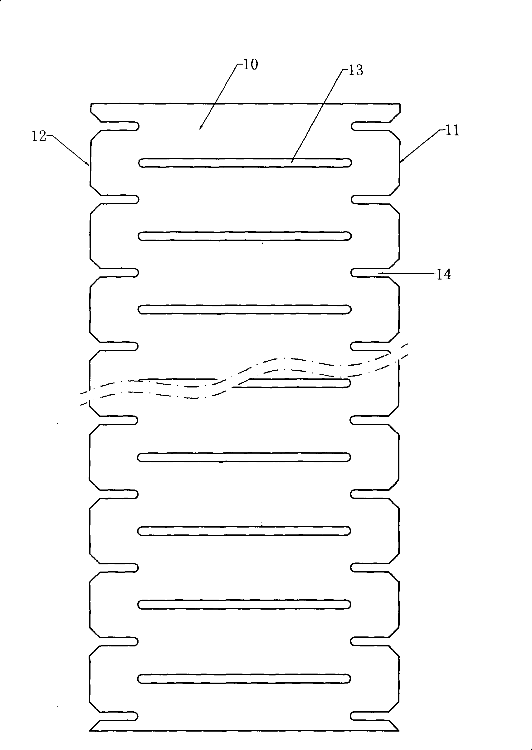
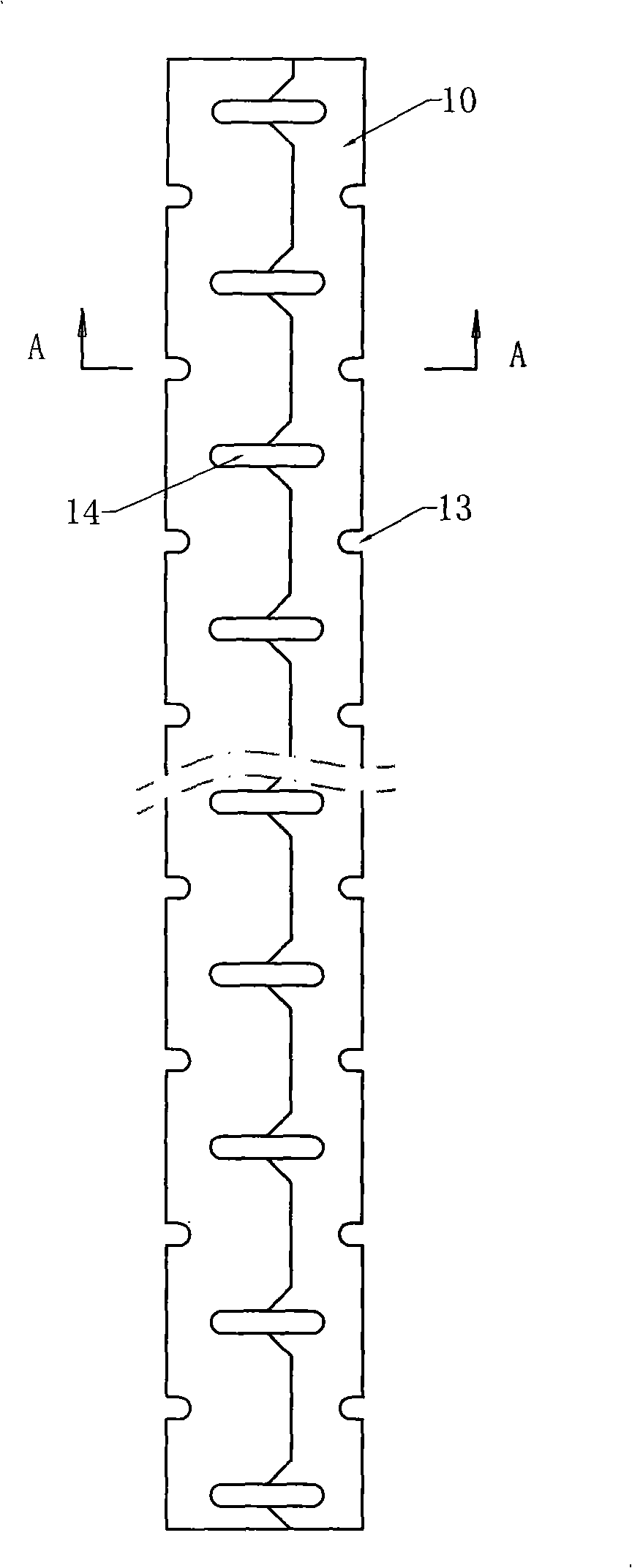
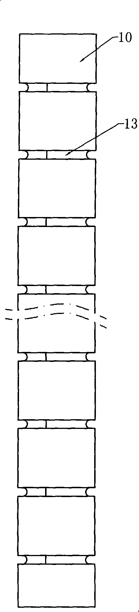
[0033] refer to Figure 1-Figure 4 , the cable protective sleeve is made of plastic sheet 10 curled, and the longitudinal edges 11 and 12 on both sides are laminated inside and outside to form a cross-section of The inner and outer overlapping width of the two longitudinal edges 11 and 12 accounts for 1 / 5 of the width of the plastic sheet. On the cylinder wall, there are evenly distributed horizontal "one"-shaped slots 13, and the "one"-shaped The length of the slot accounts for 3 / 4 of the width of the plastic sheet. On the longitudinal edges of the two sides, there are respectively symmetrically and evenly distributed transverse notches 14, and the notches and the slots are arranged alternately.

[0034] Its production method is: 1) adopt PE material to produce sheet, then use shearing equipment to punch out "one" shaped slot 13 and notch 14, such as figure 1 Shown; 2) Use coiled tube equipment to figure 1 The sheet materi...

Embodiment 2

[0035] Embodiment 2, lead clip.

[0036] refer to Figure 5-Figure 9 , the lead clip is composed of a left clip 220 , a right clip 210 and an elastic buckle 30 . The upper part 221 of the left clip and the upper part 211 of the right clip constitute the thread shuttle head; the concave cavity 222 of the left clip and the concave cavity 212 of the right clip constitute a circular binding hole; the bottom 224 of the left clip and the right clip The lower part 214 of the bottom constitutes the handle of the lead clip, and the handle can be controlled to open or close the lead clip; the elastic buckle 30 is installed on the left clip through the through hole 225 on the left clip handle and the through hole 215 on the right clip handle. On the sheet 220 and the right clip 210, the ends of the elastic buckle 30 are fastened respectively on the rib 226 of the left clip and the rib 216 of the right clip, the groove 223 on the left clip and the rib on the right clip 213 constitutes t...


PUM


Abstract

The invention relates to a cable protective sleeve used for families, offices and engineering and a lead clamp thereof. The lead clamp belongs to an auxiliary component and the cable protective sleeve belongs to a main component; the cable protective sleeve is made of a plastic sheet coil pipe, the longitudinal edges of two sides of the plastic sheet coil pipe are superimposed from inside to outside so as to form a cylinder; horizontal I-shaped groove holes are uniformly distributed on the cylinder wall, and the length of the horizontal I-shaped groove holes is 2/3 to 4/5 of the width of a plastic sheet; the lead clamp consists of a pair of plastic clamping pieces and an elastic fastener which can clamp the clamping pieces; the upper parts of the clamping pieces are respectively provided with a lead shuttle end, and the middle parts are respectively provided with a binding wire hole; a pivoted device is arranged below the binding wire hole; and a handle is arranged at the lower part of the pivoted device. The cable protective sleeve has the advantages of adopting environment-friendly and regenerative material, having elegant and beautiful appearance, being suitable for indoor and outdoor to use, having simple structure and various specifications and being capable of effectively protecting the cable.

Description

Technical field: [0001] The invention relates to a kind of loose arrangement and fixation of cables used in home, office and engineering, especially capable of safe and effective anti-stepping, sun-proof, anti-interference, natural and automatic drainage, flame retardant, environmental protection, and achieves a generous and beautiful appearance. And the cable protective cover and its lead clip with easy and safe installation. Background technique: [0002] At present, there are power cords and connection cords for various products such as TVs, DVDs, VCDs, and audios for household use; various power cords and connecting cords for various products such as computer peripherals, multimedia, and telephones for office use. Connecting wires; then to various engineering cables such as audio and video, public broadcasting, multimedia, security and network used in engineering, they are arranged and fixed by cable tying or cable boxes after the cables are arranged. It is to prevent t...

Claims


Application Information

Patent Timeline
Patent Type & Authority Applications(China)
IPC IPC(8): H02G3/04H02G3/02
Inventor 许福章
Owner 许福章
Why Eureka
Try Eureka