

Doherty envelope tracking power amplifier and method for treating radio frequency signal
A power amplifier, radio frequency signal technology, applied in power amplifiers, improving amplifiers to reduce nonlinear distortion, etc., can solve the problems of real-time setting of carrier amplifiers, low efficiency of carrier amplifiers, etc., to achieve the effect of improving linearization and improving efficiency
- Summary
- Abstract
- Description
- Claims
- Application Information
AI Technical Summary
Problems solved by technology
Method used
Image

Examples
Embodiment Construction
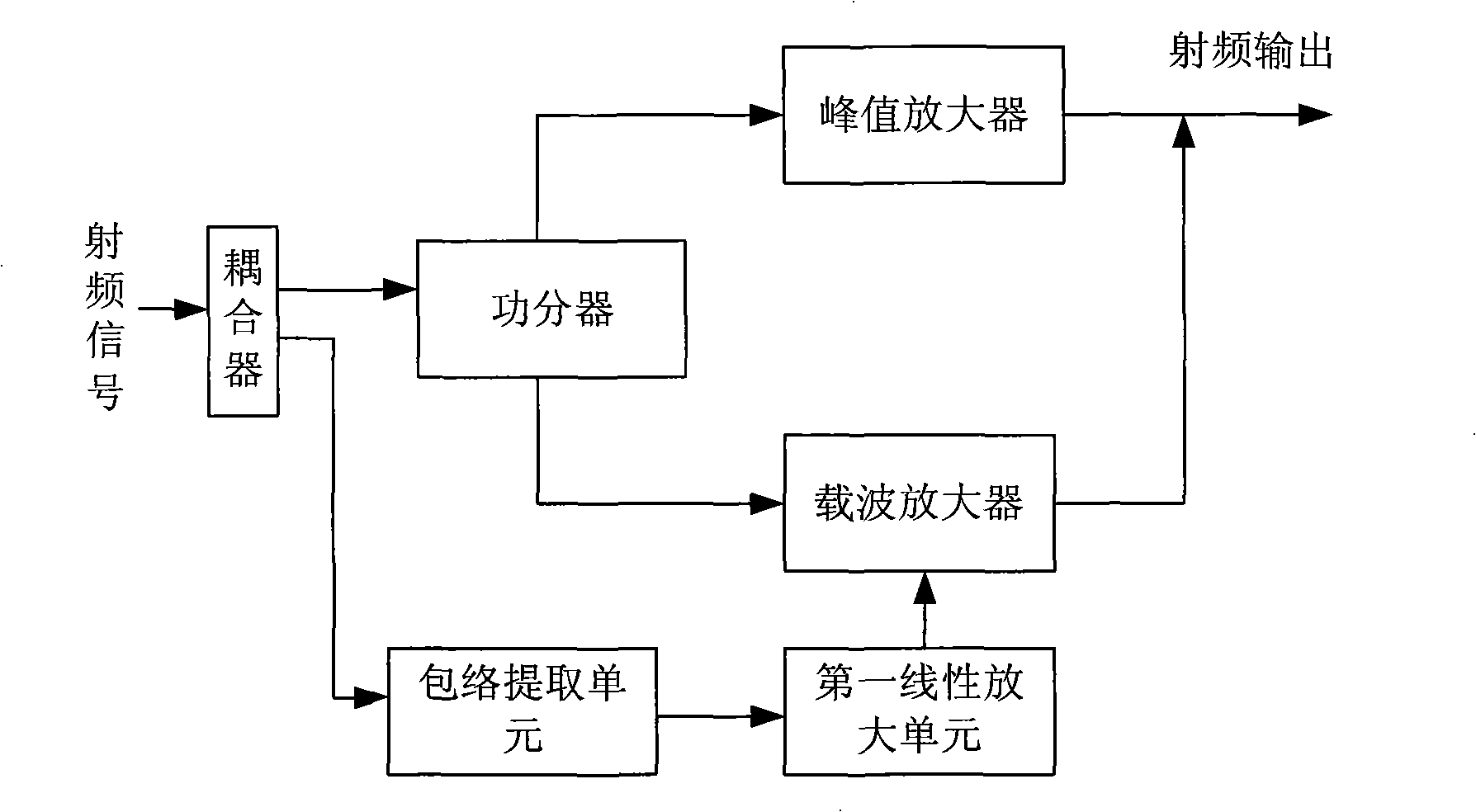
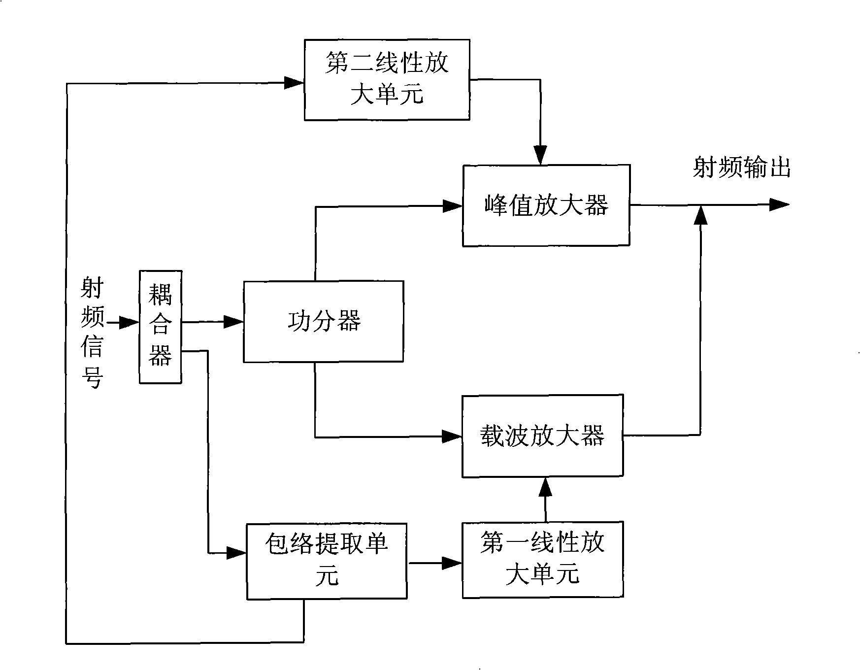
[0028] The Doherty envelope tracking power amplifier and its method for processing radio frequency signals of the present invention extract the envelope signal from the input radio frequency signal through the envelope extraction unit, and convert it into a carrier amplifier working grid after being amplified by the first linear amplifying unit Pressure value; the carrier amplifier can change the envelope of the input radio frequency signal, and under the condition that the output signal gain is basically unchanged, the linearization of the output signal can be optimized in real time, which improves the linearization of the output signal of the carrier amplifier. This in turn improves the efficacy of the Doherty envelope tracking power amplifier.
[0029] The present invention will be described in detail below in conjunction with the accompanying drawings and specific embodiments.
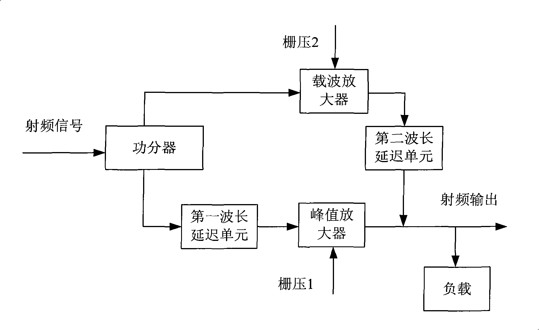
[0030] The present Doherty envelope tracking power amplifier, as figure 2 , including a power...
PUM
 Abstract
Description
Claims
Application Information