Method for controlling a hybrid drive

A technology of hybrid drive and clutch, which is applied in the direction of control device, power device, traction driven by engine, etc., can solve the problem of no synchronization and achieve the effect of comfortable control

Active Publication Date: 2009-09-09
ROBERT BOSCH GMBH
View PDF0 Cites 12 Cited by
  • Summary
  • Abstract
  • Description
  • Claims
  • Application Information

AI Technical Summary

Problems solved by technology

But because in these starter generators the electric machine is fixedly connected to the crankshaft of the car, the problem of synchronization in operation is not raised

Method used


Image

  • Method for controlling a hybrid drive
  • Method for controlling a hybrid drive
  • Method for controlling a hybrid drive

Examples


Embodiment Construction

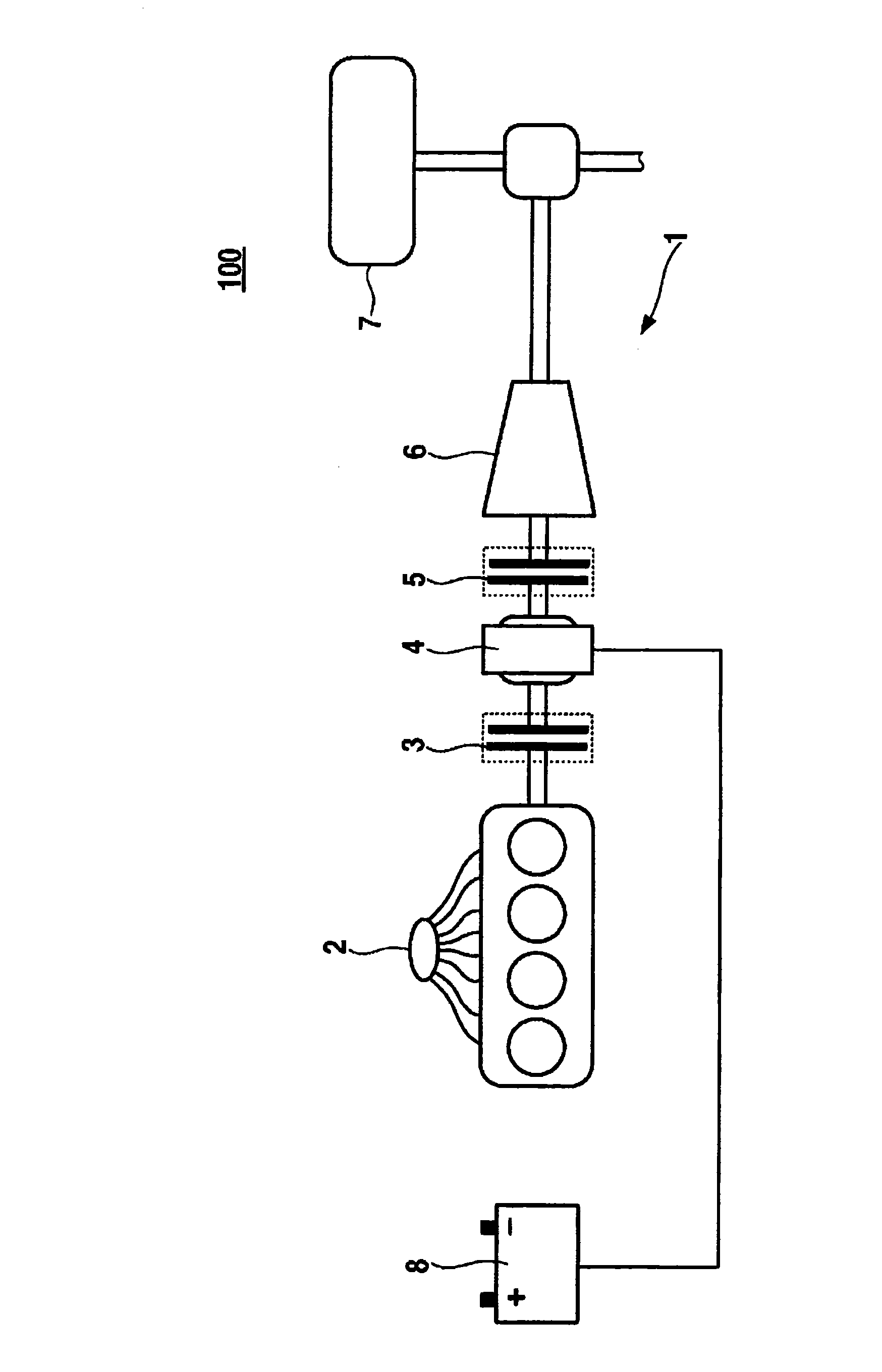
[0012] Embodiments of the present invention will be explained in detail below with reference to the accompanying drawings. figure 1 A schematic diagram of a motor vehicle 100 with hybrid drive 1 is shown. The hybrid drive 1 includes a conventional internal combustion engine 2 and an electric machine 4 . A first clutch 5 is arranged between the electric machine 4 and the schematically shown drive train designated with the reference numeral 6 . A second clutch 3 is arranged between the internal combustion engine 2 and the electric machine 4 . This is preferably a proportional clutch. The chassis of the motor vehicle 100 is represented by the wheels 7 and part of the axle with the differential. A storage battery, which supplies energy to the electric machine 4 , is denoted by reference numeral 8 . Other components of the automotive circuit are in figure 1 not shown in . exist figure 1 The hybrid drive 1 shown in FIG. 1 enables a purely electric drive of the motor vehicle 1...


PUM


Abstract

The invention relates to a method for controlling a hybrid drive of a vehicle (100), comprising at least one internal combustion engine (2) and at least one electric machine (4). The invention further comprises a first clutch (5), which is arranged between the electric machine (4) and the drive train (6) of the vehicle (100), and a second clutch (3), which is arranged between the electric machine (4) and internal the combustion engine (2). According to the invention, operating parameters of the hybrid drive (1) are controlled as a function of the driver's request.

Description

technical field [0001] The invention relates to a method for controlling a hybrid drive of a motor vehicle according to the preamble of claim 1 . Background technique [0002] A hybrid drive of this type comprises at least one internal combustion engine, at least one electric machine and at least one clutch arranged between the internal combustion engine and the electric machine and between the electric machine and a connected drive train of the motor vehicle. In the context of further improvements of existing drive concepts in the automotive sector with regard to energy consumption optimization, reduction of emissions and improvement of the subjective driving experience, hybrid drives are becoming more and more important. Besides the internal combustion engine, these hybrid drives have at least one other drive source which does not operate with fossil fuels. By means of a suitable operating strategy, the advantages of the different drive sources can be optimally utilized a...

Claims


Application Information

Patent Timeline
Patent Type & Authority Applications(China)
IPC IPC(8): B60W20/00B60K6/48B60W10/02B60W10/06B60W10/08B60L50/16
CPCY02T10/6286B60W2540/103B60W10/06B60W2710/025B60K6/48B60W10/02B60W10/08B60W20/00Y02T10/6221B60L50/16Y02T10/62Y02T10/7072B60W20/40Y02T10/70
Inventor R·申克O·凯弗T·朱恩曼
Owner ROBERT BOSCH GMBH
Why Eureka
Try Eureka