Check patentability & draft patents in minutes with Patsnap Eureka AI!

Network image synthesizing display system

A technology for image synthesis and display systems, applied in two-way working systems, closed-circuit television systems, TV system components, etc., can solve problems such as increased network load, bottlenecks, and high processing load of display devices, and achieve the goal of reducing network load Effect

Inactive Publication Date: 2011-03-09
MITSUBISHI ELECTRIC CORP
View PDF1 Cites 0 Cited by
  • Summary
  • Abstract
  • Description
  • Claims
  • Application Information

AI Technical Summary

Problems solved by technology

[0004] However, in a system that creates a synthetic video from video captured by a plurality of cameras, transmits the synthetic video to a remotely installed display device via a network, and displays the received synthetic video on the display device, the number of cameras is limited. increases, the load of image synthesis processing becomes larger, so image synthesis processing becomes the bottleneck of system operation
That is, there is a problem that the number of camera images that can be processed simultaneously is limited by the processing capability of image synthesis
[0005] In addition, since the data volume of the synthesized video increases with the increase in the number of cameras, there is also a problem that the network load increases when the synthesized video is sent over the network.
In addition, the display device is composed of a plurality of display devices. When displaying a composite video by combining the display images of the plurality of display devices, each display device needs to divide / select the received composite video according to its own display area. Part of the processing, there is also a problem that the processing load on the display device also increases

Method used


Image

  • Network image synthesizing display system
  • Network image synthesizing display system
  • Network image synthesizing display system

Examples


Embodiment approach 1

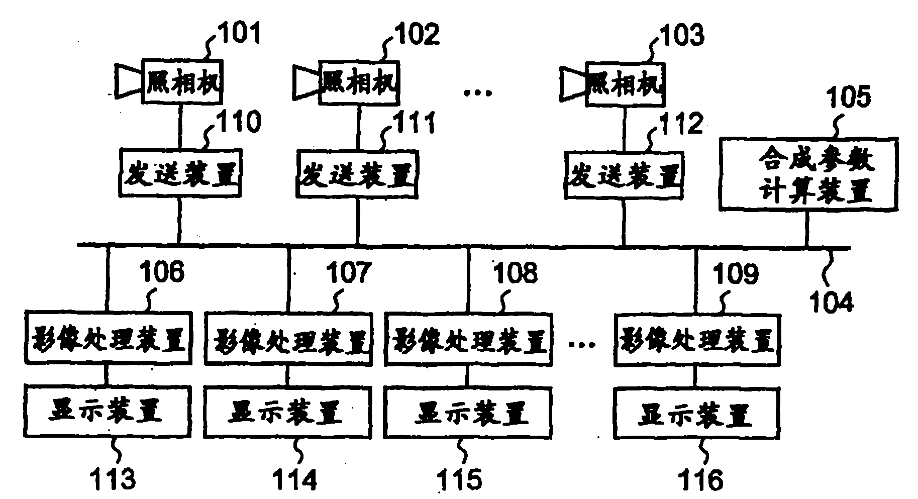
[0031] according to figure 1 The configuration of the network video composite display system according to Embodiment 1 of the present invention will be described. The network image synthesis display system includes: cameras 101, 102, 103 for taking images; the images taken by these cameras are multicasted to the synthesis parameter calculation device 105 and image processing devices 106, 107, 108, 109 via the network 104 The sending device 110, 111, 112; calculate the synthesis parameter used when combining multiple camera images, and send the calculated synthesis parameter to the image processing device 106, 107, 108, 109 via the network 104 to calculate the synthesis parameter Device 105; According to the camera images received from the sending devices 110, 111, 112 and the composite parameters received from the composite parameter calculation device 105, image processing devices 106, 107, 108, 109 for synthesizing and displaying images; and displaying the synthesized Displ...

Embodiment approach 2

[0065] In Embodiment 1, the synthesis parameter calculation unit 105 calculates the synthesis parameters only once as the initial processing of the network video synthesis display system, and the video processing units 106, 107, 108, and 109 apply the synthesis parameters to all periods of system operation. It is operating during video synthesis processing. Therefore, if there is a setting change such as a change in the installation position of each camera or a change in the object to be photographed during the operation of the system, since the synthesis parameters calculated before the setting change are continued to be used, the camera after the setting change Discrepancy occurs in the display of the display devices 113 , 114 , 115 , and 116 . In contrast, the network video composite display system according to Embodiment 2 can normally display a composite video even when the installation positions of the cameras are changed during system operation. The configuration and c...

Embodiment approach 3

[0075] In Embodiments 1 and 2, the synthesis parameter calculation device calculates the synthesis parameter when the system is operating, and transmits the synthesis parameter to each information processing device. In contrast, the network video synthesis display system in Embodiment 3 can independently set synthesis parameters calculated by other means instead of the synthesis parameter calculation means for each information processing device, and each information processing device performs video synthesis using the synthesis parameters. .

[0076] Figure 14 It is a diagram showing the system configuration of the network video composite display system in the third embodiment. In addition, in Figure 14 in, for with figure 1 The same or corresponding parts are assigned the same reference numerals. Hereinafter, the operation will be described focusing on differences from the first embodiment.

[0077] First, the composition parameters used in the respective video process...


PUM


Abstract

The present invention provides a network image synthesizing display system. Camera images taken by a plurality of cameras (101, 102 and 103) are multicast and sent via the network by a plurality of sending devices (110, 111 and 112). A synthetic parameter calculating device (105) uses the camera images and calculates such synthetic parameters in a manner to correspond to image processing devices (106, 107, 108 and 109) as are necessary for synthesizing the display images to be displayed in display devices (113, 114, 115 and 116), and sends those synthetic parameters to the image processing devices (106, 107, 108 and 109). On the basis of those synthetic parameters, the image processing devices (106, 107, 108 and 109) synthesize the camera images into display images. As a result, the display images are distributively synthesized by the individual image processing devices.

Description

technical field [0001] The present invention relates to a network image composite display system for displaying images captured by a plurality of cameras connected to a network on a plurality of display devices connected to the network. Background technique [0002] There are various types of devices that have a function of displaying images captured by a remote camera, including televisions. In addition, in recent years, with the development of networks such as the Internet, techniques for displaying images captured by cameras connected to the network on personal computers have also been popularized. In addition, a display system has been proposed that displays a wider range of images than can be imaged by a single camera by combining images captured by a plurality of cameras (for example, Patent Document 1). In addition, in order to display a large video, a multi-large-screen device that connects video from a plurality of display processing devices to display as one large...

Claims


Application Information

Patent Timeline
Patent Type & Authority Patents(China)
IPC IPC(8): H04N7/18H04N5/232H04N7/173H04N5/265H04N5/262H04N23/90
CPCH04N7/181H04N5/265H04N5/247H04L12/18H04N23/90
Inventor 原田雅之吉田浩椿泰范
Owner MITSUBISHI ELECTRIC CORP
Features
  • R&D
  • Intellectual Property
  • Life Sciences
  • Materials
  • Tech Scout
  • Unparalleled Data Quality
  • Higher Quality Content
  • 60% Fewer Hallucinations
Learn More