
Spirally driven walking robot in pipe

A walking robot and spiral-shaped technology, applied in the field of robots, can solve problems such as low efficiency, difficult processing, and difficulty in popularization and application, and achieve the effects of low processing and manufacturing costs, simple structure, and stable operation

Inactive Publication Date: 2009-09-16
JIANGSU POLYTECHNIC UNIVERSITY
View PDF1 Cites 41 Cited by
  • Summary
  • Abstract
  • Description
  • Claims
  • Application Information

AI Technical Summary

Problems solved by technology

At present, the driving methods of the moving mechanism of pipeline robots at home and abroad include motor drive, piezoelectric drive, electromagnetic drive, pneumatic drive, hydraulic drive, etc.; and the walking mode of robots can be divided into inertial impact walking, creeping crawling, elastic driving walking and wheeled driving. Walking, etc., through comparative research, it is found that the existing pipeline robots have various deficiencies such as: complex drive principle and structure, difficult processing, low efficiency, and difficult to achieve for pipelines with small diameters, so that they Difficult to be widely applied
Application number [200710050056.8] discloses a circular pipeline robot driven by a spiral, which adopts a simple spiral drive and can be changed in diameter. A certain length, therefore, it is difficult to apply to the pipeline with large curvature

Method used


Image

  • Spirally driven walking robot in pipe
  • Spirally driven walking robot in pipe
  • Spirally driven walking robot in pipe

Examples


Embodiment Construction

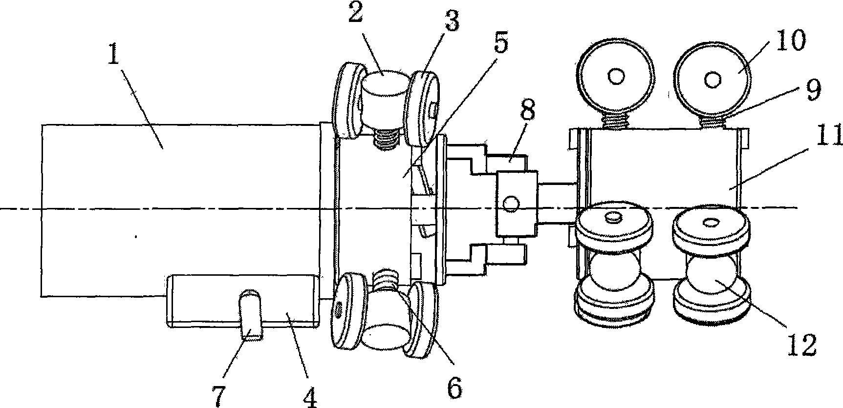
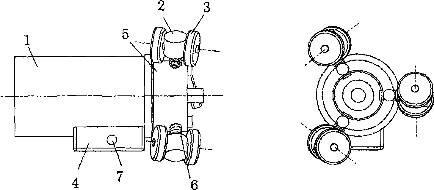
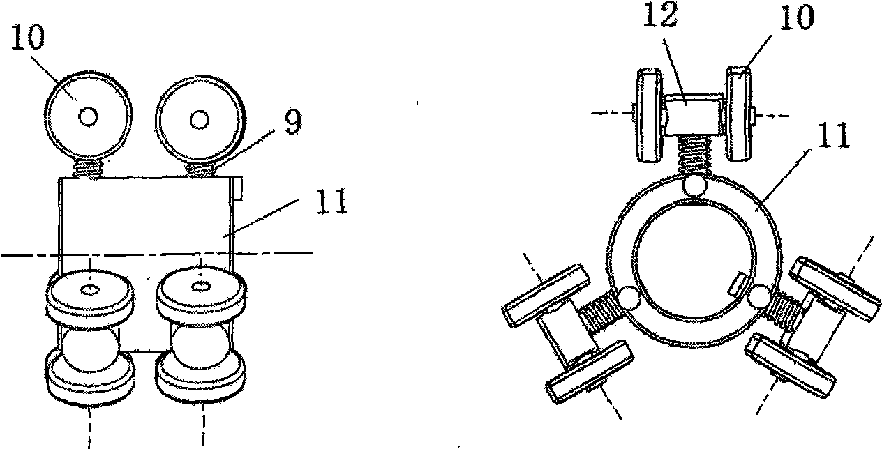
[0010] As an example, such as figure 1 Shown, the present invention can be made up of power drive unit, walking guide and the universal joint 8 that connects these two parts, power drive unit ( figure 2 ) is composed of a circular rotor 5 driven by a motor 1. Three sets of symmetrically arranged wheel frames 2 are installed on the outer wall of the circular rotor 5, and two wheels 3 are installed on each wheel frame 2. The rotation axis of the wheels 3 is in line with the rotor The axis of 5 is an acute angle of inclination; and the walking guide ( image 3 ) is composed of three sets of symmetrically arranged guide wheel frames 12 on the outer wall of a cylinder or cylindrical body 11, and two wheels 10 are also installed on each group of guide wheel frames 12, and the rotation axis of the wheels 10 is in line with the column or cylindrical body The axes of 11 are perpendicular to each other. The link between the two parts of the power drive and the walking guide can be a ...


PUM


Abstract

The invention provides a spirally driven walking robot in a pipe, which consists of a power-driven device, a walking guide device and a universal joint (8) connecting the power-driven device and the walking guide device; the power-driven device is formed by a motor (1) driving a circular rotor (5); the outer wall of the circular rotor (5) is respectively provided with three groups of symmetrically distributed wheel carriers (2); each group of wheel carrier (2) is provided with two wheels (3), and the rotating axes of the two wheels forms an acute elevation angle with the axes of the rotor (5); the walking guide device consists of three groups of symmetrically distributed guide wheel carriers (12) which are arranged on the outer wall of a cylinder or a cylindrical body (11); each group of guide wheel carrier (12) is provided with two wheels (10), and the rotating axes of the two wheels is vertical to the axes of the cylindrical body (11); and the wheel carriers (2) on the rotor (5) of the power-driven device and the guide wheel carriers (12) on the cylinder or the cylindrical body (11) of the walking guide device are all floating bodies, and certain radial dilation generated by a spring (9) is used to make all wheels on the wheel carriers (2) and the guide wheel carriers (12) always attach to the inner wall of the pipe. The motor drives the walking robot in the pipe to advance or retreat along the axes direction of the pipe.

Description

technical field [0001] The invention relates to a robot walking in pipelines, that is to say, it provides a new type of pipeline walking robot for the detection, cleaning, repairing and other operations of various industrial transportation pipelines. Background technique [0002] As an important carrier for long-distance transportation of oil, natural gas, and tap water, pipelines play an increasingly prominent role in modern industrial construction and daily life. Considering the stability, safety, and work efficiency of pipeline installation, maintenance, and testing, pipelines Operations increasingly require the use of pipeline robots as mobile carriers to replace manual operations. At present, the driving methods of the moving mechanism of pipeline robots at home and abroad include motor drive, piezoelectric drive, electromagnetic drive, pneumatic drive, hydraulic drive, etc.; and the walking mode of robots can be divided into inertial impact walking, creeping crawling, ...

Claims


Application Information

Patent Timeline
Patent Type & Authority Applications(China)
IPC IPC(8): B62D57/036B61F13/00B61B13/10
CPCF16L55/32
Inventor 沈惠平李航曲靖祎方琳孔金山俞成龙高志鹏
Owner JIANGSU POLYTECHNIC UNIVERSITY
Learn More