

Method and system for controlling elevator by adopting permanent magnet synchronous motor
A permanent magnet synchronous motor technology, applied in the field of elevator control, can solve problems such as motor noise pollution, achieve the effects of eliminating sound, improving safety, and avoiding poor contact contact
- Summary
- Abstract
- Description
- Claims
- Application Information
AI Technical Summary
Problems solved by technology
Method used
Image


Examples
Embodiment Construction
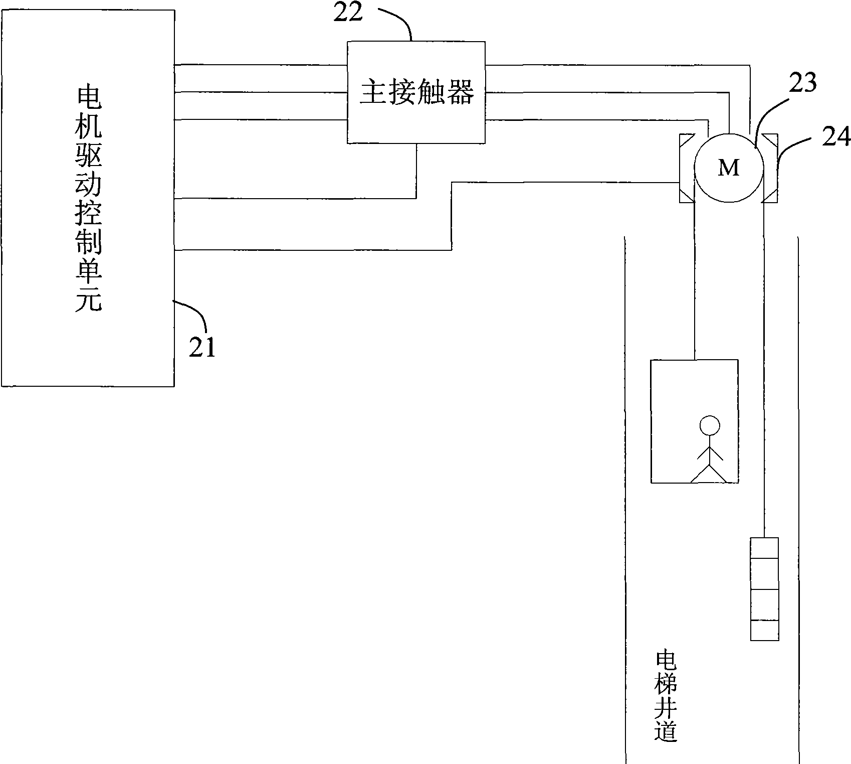
[0033] Such as figure 2 Shown is a structural diagram of a system embodiment of the present invention using a permanent magnet synchronous motor to control an elevator. In this embodiment, the system includes a motor 23 , a brake 24 , a motor drive control unit 21 , and a main contactor 22 , wherein the motor drive control unit 22 is connected to an external power source and supplies power to the motor 23 through the main contactor 22 . The motor drive control unit 21 is also used to receive feedback information from the brake 24 , the motor 23 , and the main contactor 22 , and control the closing and opening of the main contactor 22 and the opening and closing of the brake 24 .
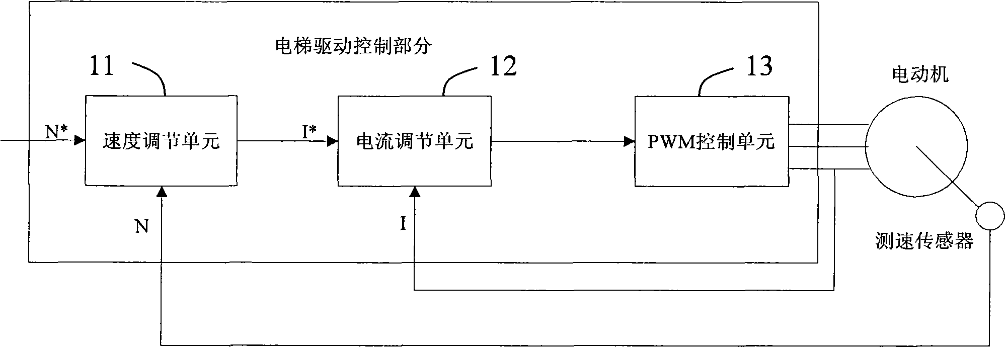
[0034] Such as image 3 Shown is a schematic structural diagram of the motor drive control unit 21 . The motor drive control unit 21 includes a speed regulation unit 211 , a current regulation unit 212 , a current control unit 213 and a motor starting unit 214 . The speed regulation unit 211 is us...
PUM
 Abstract
Description
Claims
Application Information