Multi-mode satellite positioning navigation terminal antenna

A technology for positioning navigation and terminal antennas, applied to antennas, antennas suitable for movable objects, beacon systems using radio waves, etc., can solve the problem of not being able to apply microstrip patch antennas, and not improving Low elevation angle gain and other issues, to achieve the effect of low cost, high low elevation gain, and good circular polarization performance

Inactive Publication Date: 2012-05-30
DALIAN MARITIME UNIVERSITY
View PDF5 Cites 0 Cited by
  • Summary
  • Abstract
  • Description
  • Claims
  • Application Information

AI Technical Summary

Problems solved by technology

Therefore, without improving the low elevation gain of the microstrip patch antenna, it is impossible to apply the microstrip patch antenna to the navigation terminal antenna, so as to meet the requirements of the multi-mode satellite positioning navigation terminal antenna

Method used


Image

  • Multi-mode satellite positioning navigation terminal antenna
  • Multi-mode satellite positioning navigation terminal antenna
  • Multi-mode satellite positioning navigation terminal antenna

Examples


Embodiment Construction

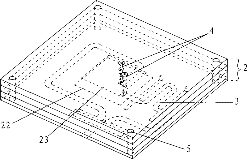
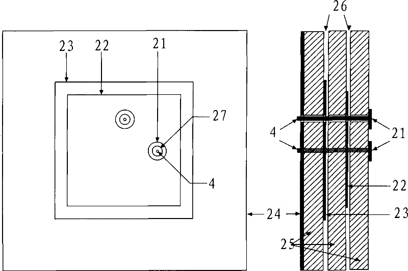
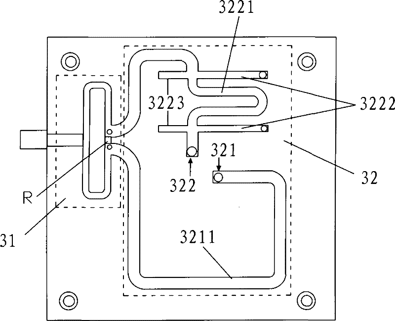
[0034] like Figure 1 to Figure 4 As shown, the multi-mode satellite positioning and navigation terminal antenna of the present invention includes a laminated microstrip patch antenna 2, a broadband orthogonal feed network 3 and a connection probe 4; the laminated microstrip patch antenna 2 includes a capacitor plate 21, an upper layer patch Sheet 22, lower patch 23, ground 24, dielectric substrate 25, compensating air layer 26 and protection hole 27 (such as figure 2 shown); the upper patch 22 is coupled and fed through the capacitor plate 21, and works in the high frequency band (1559-1610MHz), and is used to receive satellite positioning and navigation signals near the L1 frequency band; the lower patch 23 is coupled and fed through the upper patch 22 , working in the low frequency band (1164-1239MHz), used to receive satellite positioning and navigation signals near the L2 and L5 frequency bands. A coupling capacitor is formed between the capacitive plate 21 and the uppe...


PUM


Abstract

The invention discloses a multi-mode satellite positioning navigation terminal antenna. The multi-mode satellite positioning navigation terminal antenna is characterized in that the antenna comprises a laminated microstrip patch antenna, a broadband orthogonal feed network and a connecting probe; the structure of the laminated microstrip patch antenna comprises a capacitor plate, an upper-layer patch, a lower-layer patch and ground from top to bottom; medium substrates are respectively arranged among the capacitor plate, the upper-layer patch, the lower-layer patch and the ground; simultaneously, air compensating layers are arranged among the medium substrate fixed with the capacitor plate, the medium substrate fixed with the upper-layer patch and the medium substrate fixed with the lower-layer patch; and the broadband orthogonal feed network consists of a Wilkinson power splitter and a 90-degree broadband phase shifter and is fixed on the medium substrate under the ground. The antenna has the characteristics of low cost, wide antenna beam, low elevation, high gain, and the like and is quite suitable for application to a high-precision satellite positioning navigation and time service system.

Description

technical field [0001] The invention relates to a multi-mode satellite positioning navigation terminal antenna, in particular to a receiving antenna used in high-precision satellite positioning navigation and timing systems. Background technique [0002] In 2008, my country's "Beidou" satellite positioning and navigation system played a significant role in earthquake relief, and satellite positioning and navigation has attracted more and more people's attention. Likewise, GPS in the United States, GLONASS in Russia, and GALILEO in Europe are being widely used. The "Beidou" satellite positioning and navigation system independently developed by my country has also met the needs of users in my country and its surrounding areas for satellite positioning and navigation, and plans to gradually expand to a global satellite positioning and navigation system in 2010. The most common car satellite positioning navigator currently on the market can only receive GPS signals in the L1 fr...

Claims


Application Information

Patent Timeline
Patent Type & Authority Patents(China)
IPC IPC(8): H01Q3/30H01Q1/38H01Q1/27H01Q13/08G01S1/04
Inventor 房少军王钟葆付世强吕善伟
Owner DALIAN MARITIME UNIVERSITY
Why Eureka
Try Eureka