
Reciprocating compressor of refrigerating machine

A refrigerating machine and reciprocating technology, which is applied in the field of refrigerating compressors, can solve problems such as easy decomposition and double bonds are easy to break, and achieve the effects of improving energy efficiency, improving compression efficiency, and preventing global warming

Inactive Publication Date: 2009-09-16
SANDEN CORP
View PDF1 Cites 11 Cited by
  • Summary
  • Abstract
  • Description
  • Claims
  • Application Information

AI Technical Summary

Problems solved by technology

However, new alternative refrigerants containing double bonds are prone to break down of their double bonds under high-temperature use conditions, and thus are easily decomposed at the discharge temperature of the refrigerant

Method used


Image

  • Reciprocating compressor of refrigerating machine
  • Reciprocating compressor of refrigerating machine
  • Reciprocating compressor of refrigerating machine

Examples


Embodiment Construction

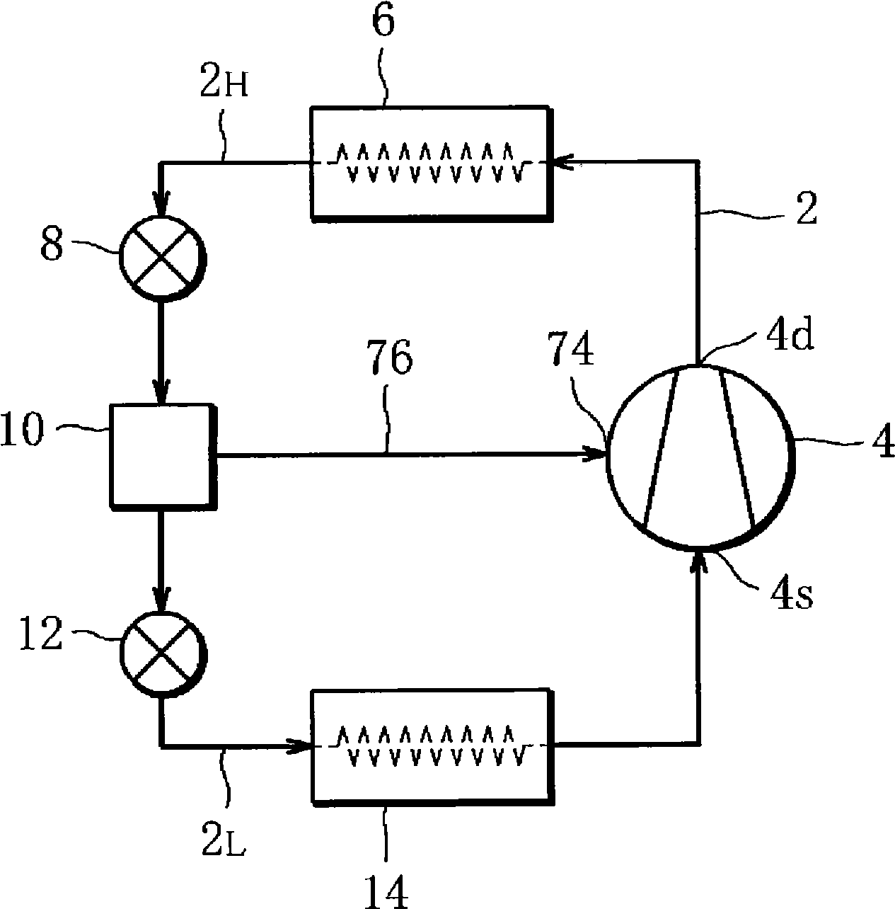
[0020] figure 1 The refrigerating machine is installed in the air-conditioning system for the vehicle, and includes the circulation path 2 for the refrigerant. A compressor 4 , a condenser 6 , a first expansion valve 8 , a gas-liquid separator 10 , a second expansion valve 12 , and an evaporator 14 are sequentially inserted into the circulation path 2 . The compressor 4 compresses and discharges the refrigerant, and the discharged refrigerant is supplied to the condenser 6 and circulates in the circulation path 2 .

[0021] Here, the circulation path 2 has a high-pressure region 2H from the discharge port 4d of the compressor 4 to the first expansion valve 8 via the condenser 6 and from the first expansion valve 8 via the gas-liquid separator 10, the second expansion valve 12, and the evaporator. The filter 14 reaches the low-pressure region 2L of the suction port 4s of the compressor 4 .

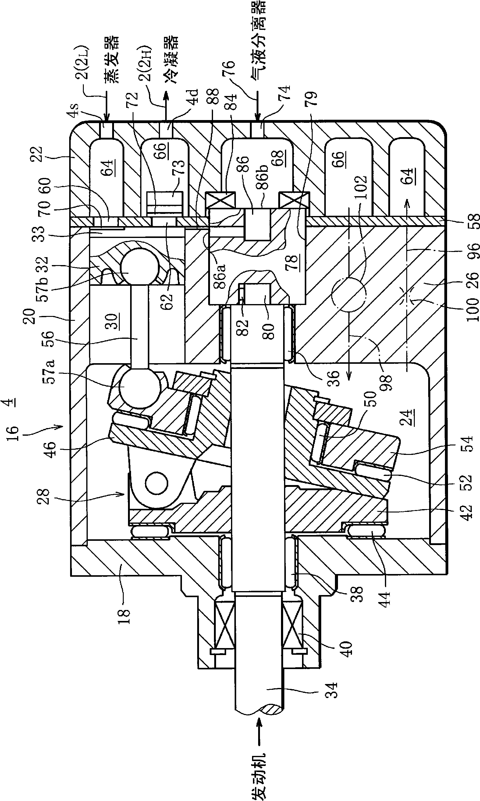
[0022] figure 2 The details of the compressor 4 are shown.

[0023] The compressor...


PUM


Abstract

A reciprocating compressor of refrigerating machine that realizes inhibition of any temperature increase of discharged refrigerant and enhancing of refrigerant compression efficiency. The reciprocating compressor of refrigerating machine is one comprising housing (16) with cylinder bore (30); piston (32) capable of reciprocating motion in the cylinder bore (30), fitted in the cylinder bore (30); intermediate pressure chamber (68) disposed within the housing (16), into which a low-temperature refrigerant is led from gas-liquid separator (10) of refrigerating machine; and rotary valve (78) disposed between compression chamber (33) and the intermediate pressure chamber (68), wherein the rotary valve (78) rotates in conjunction with main shaft (34) of the compressor and, when the refrigerant is in the stage of compression within the compression chamber (33), opens so as to jet the low-temperature refrigerant from the intermediate pressure chamber (68) into the compression chamber (33).

Description

technical field [0001] The present invention relates to a reciprocating compressor of a refrigerator, in particular to a compressor suitable for a refrigerator included in an air-conditioning system of an automobile. Background technique [0002] This reciprocating compressor includes: a cylinder block with a plurality of cylinder bores, a piston that is inserted into each cylinder bore of the cylinder block freely reciprocatingly and forms a compression chamber in the cylinder bore, and a cylinder for each piston to move in the corresponding cylinder. Spindle that reciprocates and rotates in the bore. When the main shaft is rotated, the pistons reciprocate sequentially in the corresponding cylinder bores. Such reciprocating motion of the pistons causes the refrigerant to be sucked into the corresponding compression chamber, the refrigerant to be compressed in the compression chamber, and the refrigerant to be compressed from the compression chamber. The series of processes...

Claims


Application Information

Patent Timeline
Patent Type & Authority Applications(China)
IPC IPC(8): F04B39/06F04B27/08F04B39/10F16K3/26
CPCF25B2400/23F25B2400/13F04B27/1081F04B39/062F04B27/1018F04B39/06F25B1/10F25B1/02
Inventor 寺内清
Owner SANDEN CORP
Learn More