A Novel Connection Structure and Connection Method of Cathode Wire and Cathode Frame

A cathode frame and connection structure technology, applied in the direction of electrode conveying device, electrostatic separation, etc., can solve the problems of easy disconnection at the connection point and inability to run stably for a long time, so as to overcome easy disconnection, stable connection and good performance Effect

Inactive Publication Date: 2012-02-22
CHAOYANG SHUANGLING ENVIRONMENTAL PROTECTION EQUIP
View PDF6 Cites 0 Cited by
  • Summary
  • Abstract
  • Description
  • Claims
  • Application Information

AI Technical Summary

Problems solved by technology

[0005] The technical problem to be solved in the present invention is to overcome the defects that the connection between the existing cathode wire and the cathode frame is easy to drop and cannot run stably for a long time, and to provide a new type of connection structure and method for the connection between the cathode wire and the cathode frame, which not only The connection is stable, it is not easy to drop the line, and the installation procedure is simple, which saves costs and greatly improves the working efficiency of the dust collector

Method used


Image

  • A Novel Connection Structure and Connection Method of Cathode Wire and Cathode Frame
  • A Novel Connection Structure and Connection Method of Cathode Wire and Cathode Frame
  • A Novel Connection Structure and Connection Method of Cathode Wire and Cathode Frame

Examples


Embodiment 2

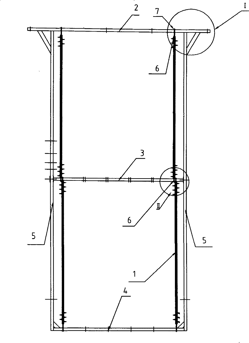
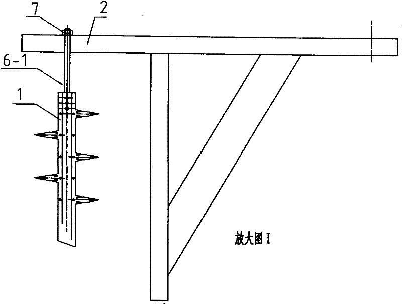
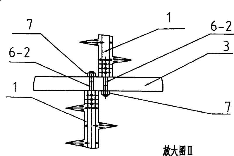
[0021] The cathode wire connection method installed between the upper frame and the middle frame: insert two long and short screws at both ends of the cathode wire, first insert one end of the long screw into the upper frame, and then move the cathode wire up to the long screw At the maximum position of the bottom, at this time, the lower end of the cathode line is one end of the short screw that can be smoothly inserted into the middle frame adjacent to the upper frame, adjust the position of the cathode line, install nuts on both ends, and weld them firmly, the long screw end The nut and the screw are welded and fixed so as to expand with heat and contract with cold, and the nut at the end of the short screw is welded and fixed with the transverse frame as a whole to prevent the rotation of the cathode wire. That is, the cathode wire can be firmly installed between the upper frame and the middle frame. Even if the nut falls off, the cathode wire will not fall off. Therefore...

Embodiment 3

[0023] Install the cathode wire between the lower frame and the middle frame, insert the end with the long screw into the lower frame, push the cathode wire down to the maximum position at the bottom of the long screw, then the top of the cathode wire is the end of the short screw and it can be smoothly Insert it into the middle frame adjacent to the lower frame, adjust the position of the cathode line, install nuts at both ends, and weld them firmly. The long screw end nut and the screw are welded and fixed so as to expand with heat and contract with cold. The frame is welded and fixed as a whole to prevent the cathode wire from rotating. That is, the cathode wire can be firmly installed between the lower frame and the middle frame. Even if the nut falls off, the cathode wire will not fall off. Therefore, the disadvantage that the connection between the cathode line and the cathode frame is easy to drop is overcome.

[0024] figure 2 It is an enlarged view of the structur...


PUM


Abstract

The invention discloses a novel cathode wire and cathode frame connection structure and connection method, comprising a cathode wire and a cathode frame. The cathode frame consists of a horizontally arranged upper frame, a middle frame, a lower frame and two vertically arranged side frame structure, the horizontal frames are respectively provided with cathode wire screw mounting holes, the cathode wire is installed between two adjacent horizontal frames, a connecting screw is respectively fixed at both ends of the cathode wire, and the connecting screw is respectively inserted into The cathode wire screw rods on two adjacent transverse cathode frames are installed in the holes and fastened by nuts. It not only has a stable connection and is not easy to drop, but also has a simple installation procedure, saves costs, and greatly improves the working efficiency of the dust collector.

Description

technical field [0001] The invention relates to a novel connection structure and connection method between a BS cathode wire and a cathode frame of an electric precipitator. Background technique [0002] The electrostatic precipitator collects the dust in the exhaust gas by electrostatic purification method, and its purification work is completed by two systems of corona electrode and sedimentation. When the dusty gas enters the inlet horn, the dusty gas is adjusted by the airflow distribution plate and the baffle plate, so that the airflow can enter the electric field more uniformly. Under the action of cross-section expansion, the air velocity decreases rapidly, and the heavier dust particles lose their velocity and settle down. The dusty gas entering the electric field will generate a corona phenomenon near the corona electrode due to the high-voltage direct current flowing through the corona electrode, and the gas will be ionized. There are a large number of electrons a...

Claims


Application Information

Patent Timeline
Patent Type & Authority Patents(China)
IPC IPC(8): B03C3/86
Inventor 王仕卓黄孝平张萍朴庆泉穆春雷温旭吴风波
Owner CHAOYANG SHUANGLING ENVIRONMENTAL PROTECTION EQUIP
Why Eureka
Try Eureka