
Pairing method of H-section steel for super-large crane beams

The invention relates to a crane beam and extra-large technology, which is applied in the field of H-section steel group alignment of extra-large crane beams, and can solve the problems of large correction amount, inconvenient hoisting adjustment and transportation, and difficulty in pressing the leveler.

Active Publication Date: 2009-09-23
MCC SHIJIU CONSTR
View PDF0 Cites 22 Cited by
  • Summary
  • Abstract
  • Description
  • Claims
  • Application Information

AI Technical Summary

Problems solved by technology

The above two methods have their own advantages and disadvantages. The vertical assembly speed is fast, but the flatness of the web is not easy to control, especially when the crane girder itself is relatively thin, it is easy to deform after temporary spot welding, and the correction amount is large; The technical requirements are easier to control, and the disadvantage is that the assembly speed is slower
For the combination of extra-large crane girders, the above two methods are not completely suitable for the following reasons: First, the thickness of the plate is large, the tonnage is large, and the hoisting adjustment and transportation are very inconvenient; , the general straightening machine is difficult to press, and the straightening effect cannot be achieved, and it is difficult for general manufacturers to find a special large-scale H-beam straightening machine, so it is necessary to study and design a simple and practical method of grouping and correction

Method used


Image

  • Pairing method of H-section steel for super-large crane beams
  • Pairing method of H-section steel for super-large crane beams
  • Pairing method of H-section steel for super-large crane beams

Examples


Embodiment Construction

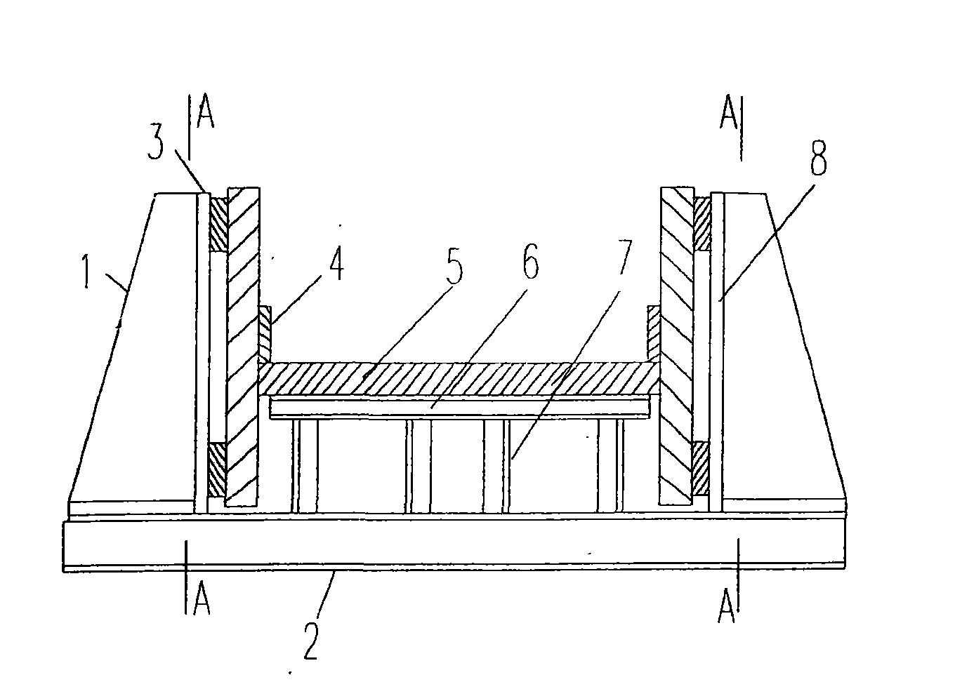
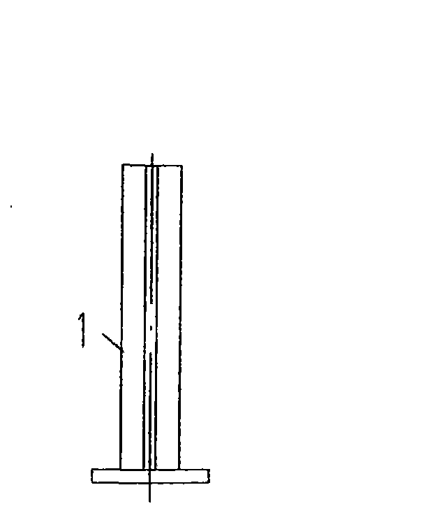
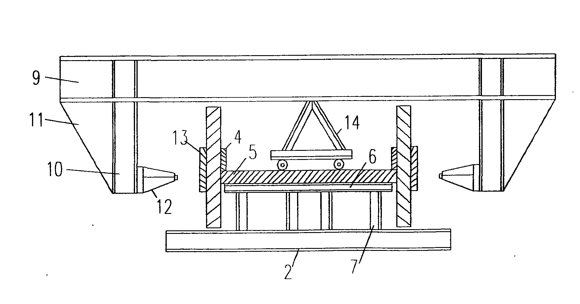
[0032] Refer below figure 1 , 2 , 3 detail the operation steps of the present invention:

[0033] 1) The tower is designed as figure 1 , 2 As shown in the assembly platform, the specific method is:

[0034] ① Flatten the assembly site, process 16 pieces of angle steel with a length of 550mm and a section of 100mm×100mm according to the design requirements, and process 4 pieces of H-shaped steel with a length of 5500mm and a section of 200mm×200mm at the same time. If there is an assembly platform in the workshop, this process can be omitted.

[0035] ② Weld 4 processed angle steels 7 vertically and equidistantly at the bottom of each processed H-shaped steel beam 1, as a platform beam for the assembly platform 2, and make 4 pieces in total.

[0036] ③ On the platform floor, according to the distance of 3 meters, lay 4 assembled platform beams in parallel horizontally and keep them on the same center line; set up a level to measure the horizontal elevation of the platform s...


PUM


Abstract

The invention relates to a method for pairing and correcting an H-section steel for super-large crane beams. The method comprises the following specific steps: setting up an assembly platform, longitudinally welding to temporarily fix H-section steel outside a central line of a base plate of a platform beam, and welding a reinforced plate; designing and manufacturing a special correcting unit; arranging a mobile roller support member in the middle of the correcting unit; respectively pairing the H-section steel of the crane beams in three sections; hoisting an upper flange slab and a lower flange slab by a traveling crane to two sides of a web plate of the crane beam on the assembly platform; tightly wedging and fixing the H-section steel by a temporary fixing device; hoisting the correcting unit to the assembly platform, and holding a joint face between the upper flange plate, the lower flange plate and the web plate; checking a joint gap, and sectionally welding between middle T-type weld seams; repeating the above correcting steps until finishing all correcting and fixing work; and releasing the temporarily fixed steel bar and starting submerged arc welding of the weld seams. The applicant manufactures and erects 12 super-large crane beams in 120t Converter-Steckel Mill Project of Angang and 4300mm Wide-thick Plate Project of Egang successively by the method and obtains remarkable effect.

Description

technical field [0001] The invention relates to a method for calibrating H-shaped steel groups of an extra-large crane girder. Background technique [0002] With the continuous improvement of the country's quality requirements for iron and steel products, the introduction and digestion of technology in the iron and steel industry and the application of advanced rolling processes have become increasingly mature. In terms of process design, due to the characteristics of the large-span workshop structure in the cooling bed area, the setting of extra-large crane beams is becoming more and more common. [0003] In the production of crane girders, the most important process is the assembly and correction of H-beams. There are usually two methods of assembly: vertical and horizontal assembly, and then corrected by H-beam straightening machine. The above two methods have their own advantages and disadvantages. The vertical assembly speed is fast, but the flatness of the web is not ...

Claims


Application Information

Patent Timeline
Patent Type & Authority Applications(China)
IPC IPC(8): B23P21/00
Inventor 马会军曾刚张庆华
Owner MCC SHIJIU CONSTR
Learn More