Induction type automatic flushing toilet

An automatic flushing and inductive technology, applied in water supply devices, flushing equipment with water tanks, buildings, etc., can solve the problem of limited life of the water release button, and achieve the effect of convenient toilet and clean toilet

Inactive Publication Date: 2009-09-23
JIAXING SHUNON ELECTRONICS TECH
View PDF5 Cites 3 Cited by
  • Summary
  • Abstract
  • Description
  • Claims
  • Application Information

AI Technical Summary

Problems solved by technology

In reality, sometimes the button is not pushed due to one reason or another; ...

Method used


Image

  • Induction type automatic flushing toilet
  • Induction type automatic flushing toilet

Examples


Embodiment Construction

[0016] The technology of the present invention will be further described below in conjunction with the accompanying drawings and specific embodiments.

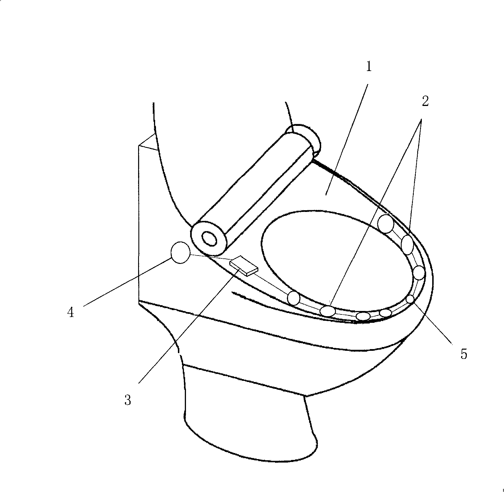
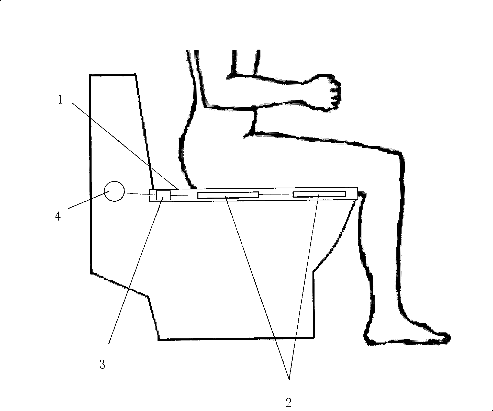
[0017] Such as figure 1 , 2 As shown, the present invention provides an induction type automatic flushing toilet, which at least includes a toilet seat 1 and a flushing control device 4, and the lower end surface of the toilet seat 1 is provided with one or more than one skin contact sensor 2 and one or more than one chip 3 , the skin contact sensor 2 is connected to the chip 3 , and the chip 3 is connected to the flush control device 4 .

[0018] The number and size of the skin contact sensors 2 are determined according to the specific application environment. The skin contact sensors 2 are arranged symmetrically or asymmetrically on both sides of the lower end surface of the toilet seat 1 .

[0019] In order to take care of men's urination, a far-infrared sensor 5 is provided at the front end of the lower end face of the t...


PUM


Abstract

The invention relates to an induction type automatic flushing toilet, at least comprising a toilet sitting plate and a flushing control device. The lower end surface of the toilet sitting plate is provided with one or more skin contact sensors and one or more chips. The skin contact sensor is connected with the chip; and the chip is connected with the flushing control device. The flushing toilet is used in such places as household washrooms, public lavatories and the like so that people relieve nature more conveniently and the washrooms become cleaner.

Description

technical field [0001] The invention relates to the technical field of manufacturing household sanitary ware, in particular to a flush toilet. Background technique [0002] The skin contact sensor determines whether it is triggered by measuring the capacitance of the human body. It uses dynamic uninterrupted scanning to capture the smallest trigger signal and filter noise to ensure that it can sense human body signals in a wide area. This technology is already very mature and is frequently used in mobile phones, MP3 and other digital devices. [0003] The prerequisite for the traditional flush toilet to work is that the water release button must be pulled. In reality, sometimes the button is not pulled for one reason or another; moreover, the life of the frequently used water release button is also very limited. At present, both urinals and squatting toilets are equipped with far-infrared sensors to realize automatic flushing. Contents of the invention [0004] The purp...

Claims


Application Information

Patent Timeline
IPC IPC(8): E03D5/10
Inventor 张擎宇
Owner JIAXING SHUNON ELECTRONICS TECH
Why Eureka
Try Eureka