Damping type self-regulating boundary gland seal

A steam seal ring, a new type of technology, applied in the field of blade top steam seal, shaft seal and diaphragm steam seal, can solve the problems of large dynamic and static gap, gas leakage, poor carbon tooth strength, etc., to achieve good sealing effect and strong sealing effect. Damping effect, unbreakable effect

Inactive Publication Date: 2009-09-23
王胜五
View PDF0 Cites 2 Cited by
  • Summary
  • Abstract
  • Description
  • Claims
  • Application Information

AI Technical Summary

Problems solved by technology

[0002] It is known that the high-temperature and high-pressure gas used to do work inside the steam turbine is sealed by the seal ring. There is a dynamic and static gap of 0.3mm to 1.2mm between the seal ring and the rotating shaft, so the sealing effect is very poor. Directly affect the operating efficiency of the steam turbine
For this reason, many new seal ring structures have appeared in the steam turbine industry in recent years. From the perspective of the size of the dynamic and static gaps, there is basically no boundary condition setting. , Either due to the small dynamic and static gap, friction and friction occur, so there is a possibility of causing vibration of the steam turbine under the working condition of the steam turbine; or when the steam turbine is in normal operation, the dynamic and static gap is too large, resulting in a large amount of gas leakage
[0003] Especially the metal sealing teeth in the known technology, once they collide with the rotating shaft, they will definitely damage the rotating shaft, and even cause the accident of the rotating shaft to bend. Therefore, in recent years, the contact seal of carbon teeth has appeared, but the strength of carbon teeth is poor. and fragile

Method used


Image

  • Damping type self-regulating boundary gland seal
  • Damping type self-regulating boundary gland seal

Examples


Embodiment Construction

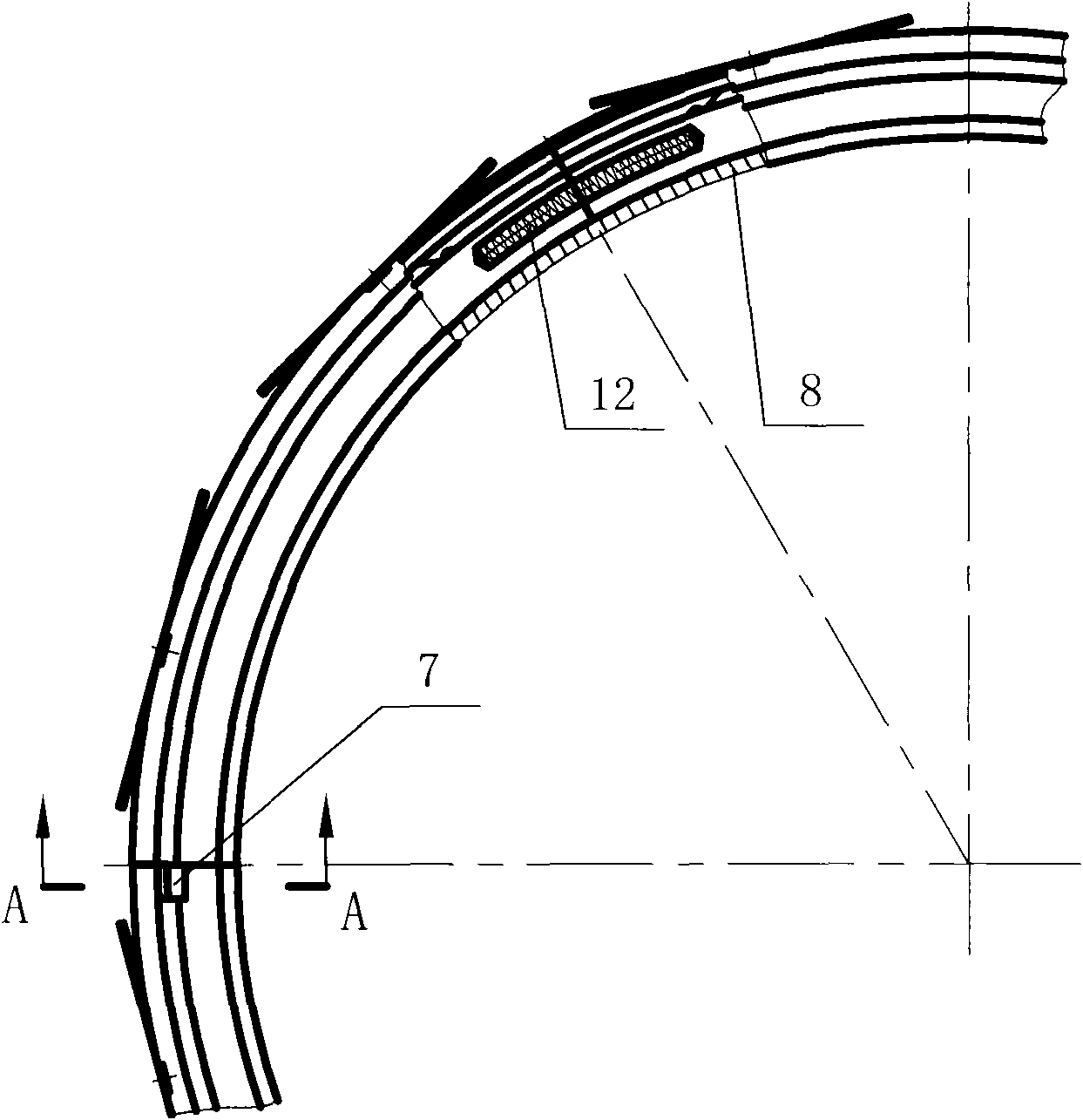
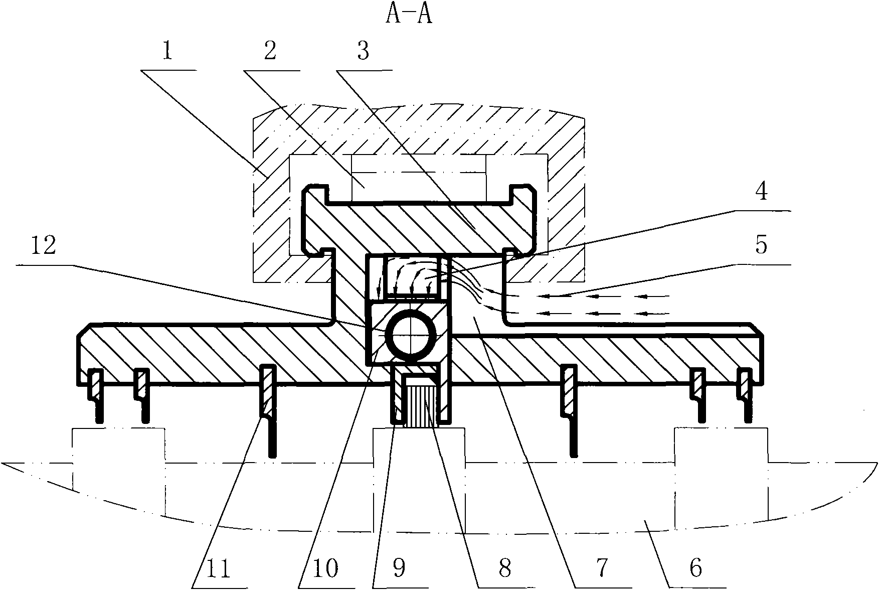
[0014] The present invention is composed of a cylinder block 1, a plate spring 2, a new seal ring 3, a high-temperature sheet spring 4, a high-temperature, high-pressure gas 5, a rotating shaft 6, a steam inlet chamber 7, a thin metal wire 8, a pressure ring 9, a slide plate 10, It consists of ferrite labyrinth teeth 11 and high temperature coil spring 12. It is characterized in that the cross-section of the multi-divided new seal ring 3 is made into a T-tail shape, and after adding a plate spring 2 on the back, it slides into the existing T-tail groove of the cylinder block 1 to form a first-stage floating. After loading onto the high-temperature thin leaf spring 4 on the back of the slide plate 10 of multiple equal parts again, cooperate in the inner groove of the novel seal ring 3, and reserve a cavity on the whole garden circumference of the slide plate 10 back, and make this cavity It communicates with the steam inlet chamber 7. Slide plate 10 is under the effect of high...


PUM


Abstract

A damping type self-regulating boundary gland seal is suitable for a steam turbine. In order to improve the efficiency of the steam turbine, a fine wire driven by a sliding plate has the two-stage floating function, and under the set boundary condition, the fine wire performs self-regulation from the upper limit of the boundary condition to the lower limit of the boundary condition with the change of the operational states. The gland seal is characterized in that: the cross section of a multi-equant novel gas seal ring is made into a T-tail shape, a board spring is additionally arranged on the back of the multi-equant novel gas seal ring, and the multi-equant novel gas seal ring slips into a T-tail groove arranged on a cylinder body; a high-temperature sheet spring is arranged on the back of the multi-equant sliding plate which is matched with an internal groove of the novel gas seal ring, so that a cavity on the back of the sliding plate is communicated with a feed steam cavity; under the action of the high-temperature sheet spring on the sliding plate, the fine wire driven by the sliding plate is contacted with a rotating shaft; and the equant joint of the sliding plate is evenly provided with a circular groove, a high-temperature spiral spring is arranged in the circular groove, and a labyrinth tooth is made of a ferrite, so that the damping type self-regulating boundary gland seal is formed.

Description

Technical field: [0001] The invention is applicable to shaft seals, vane top seals and diaphragm seals of steam turbines. Background technique: [0002] It is known that the high-temperature and high-pressure gas used to do work inside the steam turbine is sealed by the seal ring. There is a dynamic and static gap of 0.3mm to 1.2mm between the seal ring and the rotating shaft, so the sealing effect is very poor. directly affect the operating efficiency of the steam turbine. For this reason, many new seal ring structures have appeared in the steam turbine industry in recent years. From the perspective of the size of the dynamic and static gaps, there is basically no boundary condition setting. 1. Either friction friction occurs due to the small dynamic and static clearance, so there is a possibility of causing vibration of the steam turbine under the working condition of the steam turbine starting and stopping; or when the steam turbine is in normal operation, the dynamic an...

Claims


Application Information

Patent Timeline
Patent Type & Authority Applications(China)
IPC IPC(8): F01D11/02
Inventor 王胜五
Owner 王胜五
Why Eureka
Try Eureka